Chapter 7. Controlling Routing Inside the
Autonomous System
This chapter covers the following key topics:
- • Interaction of Non-BGP Routers with BGP
Routers
Brief overview of the methods by which non-BGP
routers inside an AS can reach the outside world.
- • Defaults Inside the AS: Primary/Backup
Policy
Different methods by which to avoid potential
loops when default routing inside an AS conflicts with the goal of
providing a primary and a backup link to outside the AS.
- • Defaults Inside the AS: Other BGP
Policies
Overview of routing policies other than
primary/backup, which can lead to routing loops within the AS.
- • Policy Routing
Definition
and sample of a method of controlling routes, based on traffic
source or source and destination rather than destination only.
The preceding chapter focused on the interaction between
different ASs and how BGP attributes can be manipulated to address
symmetry and load balancing. Our discussion concentrated on the
behavior of the BGP border routers that connect the AS to other ASs.
ISPs usually have most of their routers running BGP, with some
leaf nodes running IGP. On the other hand, most customers have few
routers running BGP and the majority of their internal IGP routers
running defaults toward the BGP routers. In these scenarios, it is
important to have the BGP policies go hand-in-hand with routing
inside the AS. Conflicting policies might result in routing loops if
the AS's physical layout does not complement the logical layout.
This chapter discusses the interaction of BGP routes with IGPs
inside the AS and presents the options of controlling routes via
policy routing.
Interaction of Non-BGP
Routers with BGP Routers
Non-BGP routers inside the AS can reach the outside world by
using the following two methods:
- • Injecting BGP into the IGP
- • Following defaults inside the AS
Injecting BGP into the IGP
Injecting full BGP routes into an IGP is not recommended.
Doing so will add excessive routing overhead to any IGP. Interior
routing protocols were never meant to handle more than the networks
inside your AS, plus some exterior routes from other IGPs.
This does not mean that BGP routes should never be injected into
IGPs. Depending on the number of the BGP routes and how critical the
need for them to be in the IGP, injecting partial BGP routes into
IGP may well be appropriate.
Injecting partial BGP routes into the IGP from specific points of
the AS can help direct the corresponding outbound traffic toward
specific exit points.Outbound traffic toward other Internet routes
will still have to follow defaults toward the BGP routers. Although
injecting BGP routes into the IGP seems like the optimal routing
solution, it has its drawbacks. If, for instance, the IGP is
classfull (such as RIP v1 or IGRP), information about CIDR blocks
will be lost. The other major problem is the potential instabilities
in the injected BGP routes causing instabilities in the IGP. Some
major network meltdowns have occured because the fluctuations of a
large number of external routes have caused IGPs to fail.
Following Defaults Inside an AS
The more practical solution is to follow defaults inside your AS
to the closest router that can get you outside the AS. A default
route can be injected into the AS from each autonomous system border
router. Each IGP router might receive the default route from one or
multiple routers. The IGP router chooses the best path based on the
internal cost or metric to reach the default. After the traffic
reaches the BGP routers, the traffic will propagate according to how
BGP has picked the best path.
Troubleshooting: Ch. 11, pp. 399-418. Following
Defaults Inside an AS
Figure 7-1 illustrates non-BGP routers inside an AS following
defaults to reach the closest BGP router. RTC and RTD are BGP border
routers that are injecting the default 0/0 inside AS1. RTB is an
internal BGP transit router running a full IBGP mesh with RTC and
RTD. Internal non-BGP routers, such as RTA, will receive the default
from different directions and choose the default with the smallest
IGP metric. In figure 7-1, RTA is receiving the 0/0 from RTB with a
metric of 10, from RTE with a metric of 20 (10 + 10), and from RTF
with a metric of 30 (10 + 10 + 10). RTA will prefer the default via
its link to RTB because it has the lowest internal metric (10).
After the traffic arrives at RTB, it follows the BGP routing table
to reach destinations external to the AS.

Figure 7-1 Example of
following defaults
Running IBGP inside an AS is an important element in helping to
control how traffic exits the AS and to carry transit traffic in
case there is a need to do so. Also, most of the symmetry techniques
discussed in the preceding chapter cannot be applied if multiple BGP
routers are not running IBGP. |
BGP Policies Conflicting with
Internal Defaults
Depending on the physical topology of an AS and how policies are set,
some odd situations might arise. Traffic following defaults inside the AS
toward a border router might end up in a loop, if the border routers have
some BGP policies that cause the traffic to be sent back inside the AS.
This section discusses situations where loops might occur and experiments
with possible solutions for the problem. Two cases will be considered:
Troubleshooting: Ch. 11, pp. 402-418. BGP Policies
Conflicting with Internal Defaults
- • Defaults inside the AS in conjunction with a
Primary/Backup BGP policy
- • Defaults inside the AS in conjunction with other
BGP policies
Defaults Inside the AS: Primary/Backup BGP
Policy
Consider the routing scenario in figure 7-2; AS1 is connected to the
Internet via two connections. RTC in SF is running EBGP with one provider,
whereas RTD in NY is running EBGP with another provider. Inside the AS,
RTC and RTD are running IBGP, but are not physically connected. Traffic
between RTC and RTD has to go via routers RTA and RTB.

Figure 7-2 Following default
loop situation.
Assume that RTC and RTD are both receiving full routes from their
respective providers. RTC and RTD are also injecting a 0/0 default route
inside AS1. Assume also that AS1 wants to run the primary/backup technique
to enable the NY T3 link to be the primary. AS1 would set the local
preference higher for routes coming from NY, which makes that link
primary. The SF link will be used as backup, and hence all outbound
traffic that reaches RTC will be directed back toward RTD.
RTA and RTB are interior non-BGP routers and exchange routes via IGP
with all other routers in the AS. RTA and RTB do not see any of the
exterior routes and follow defaults toward RTC and RTD according to the
lower IGP metric. Traffic for outside networks reaching RTA will end up
following the default toward RTC, whereas traffic reaching RTB will end up
following the default toward RTD.
When RTC receives the traffic, it will divert it toward RTD because of
the BGP policy that makes NY the primary link. Because RTC has no direct
connection to RTD, it will send the traffic toward RTA. RTA will receive
the traffic and send it back toward RTC, and a loop will occur.
Next, multiple scenarios are examined for avoiding the potential
looping behavior when using defaults within the AS for primary/backup
routing.
Scenario 1: Manipulating the IGP
Metric
In this scenario, we want to try to avoid a loop condition by having
all traffic for external destinations follow the default toward RTD. This
could be done by having RTC inject the 0/0 default inside the IGP with a
very high metric to make the 0/0 default for any internal router shorter
via RTD. Traffic will never go to RTC unless the NY link goes down.
Scenario 2: IBGP Path Shorter Than IGP
Path
The existence of a shorter path between the IBGP routers will make sure
that traffic will not go back over the IGP-only routers to reach its
destination. This is only required if BGP policies necessitate the
redirection of traffic from one BGP router to the other. Such situations
occur when an IBGP router does not have an external link to send the
traffic, or if it does have an external link, that link is not used as the
best path (RTC's situation in figure 7-2).
In the scenario of figure 7-2, a loop can be avoided if the border
routers RTC and RTD that run IBGP also share a physical segment such as a
serial link. Traffic coming toward RTC from RTA would be redirected over
the physical link, which provides a shorter path between RTC and RTD.
Scenario 3: Running BGP on Transit
Routers
Running BGP on all transit routers will make sure that once traffic
reaches any of these routers, it can be directed outside the AS. In the
example of figure 7-2, if RTA and RTB were to run an IBGP full mesh with
RTC and RTD, all traffic that reaches RTA or RTB will find its way out.
Note that even though AS1 might not be a transit AS, RTA and RTB are still
used to carry traffic between border routers. Internal IGP-only routers
will use the IBGP cloud to reach the outside word, as already illustrated
in figure 7-1.
Scenario 4: Who Generates the Default,
and How
Does it Get Generated?
In this scenario, a loop can be avoided if the primary router generates
the default into IGP while the secondary router does not. In this example,
RTD would inject the 0/0 into the IGP, and RTC would not. All the traffic
would follow the default toward RTD.
This solution works only in normal conditions and fails in backup
situations. If the NY link fails, the IGP routers would lose the 0/0
default. Because RTC is not generating any default, traffic to outside the
AS will fail.
The ideal situation is for RTC to inject a default into the IGP only if
the NY link fails. If the NY link goes down, RTD should stop injecting a
default into the IGP and RTC should start injecting the default into the
IGP. For this mechanism to take place, the routers must engage in the
following behaviors:
- • A BGP router should stop injecting default into
the IGP if the router's external link fails.
- • A BGP router should inject default into the IGP
only if the default it prefers points to the external link.
The first requirement can be easily achieved if the IGP allows
redistribution of the external default 0/0 into the IGP. Whenever the
external 0/0 ceases to exist, the IGP default disappears with it. The
availability and behavior of redistribution depends on what IGP you are
running and on the particular vendor implementation. The way Cisco
implements redistribution could differ from other vendors.
The second requirement mandates that a router stop generating the
default if the default it prefers comes from inside rather than outside
the AS. When the secondary router prefers the default from inside the AS,
it means that the primary link is still up. When the primary goes down,
the secondary will prefer the default from outside the AS and will inject
the default into IGP. This situation is easier to explain and understand
by example. The next two examples study the difference between a RIP- and
OSPF-generated default in a Cisco implementation.
RIP-Generated Default
In the example in figure 7-3, RTC and RTD can learn a 0/0 default or
statically configure a 0/0 default toward their respective providers. In
normal conditions, RTD will automatically (or via controlled
redistribution) inject the 0/0 into RIP. RTC will detect the presence of a
default coming from RTD and will stop generating a default. All traffic
will be directed toward RTD.

Figure 7-3 Injecting 0/0
default into RIP.
In case of a failure in the NY link, RTD will stop generating the
default into RIP. RTC will detect the loss of 0/0 via RIP and will inject
its own default.
Note that RTC is receiving the 0/0 default via EBGP, RIP, and possibly
IBGP if RTD is passing the 0/0 in the IBGP session. Because of the higher
local preference via RTD, RTC would prefer the 0/0 via IBGP. Because the
IBGP distance is 200, higher than the RIP distance of 120 (see table 5-1),
the 0/0 default via RIP is preferred.
OSPF-Generated Default
OSPF behaves differently from RIP. The BGP 0/0 cannot be passed into
OSPF via redistribution. OSPF has different hooks that enable the protocol
to generate the 0/0 into the OSPF at any time, or even better, if the
presence of a 0/0 is detected in the IP routing table. Now apply this
behavior to the example in figure 7-4.

7-4 Injecting O/O default into
OSPF.
RTD and RTC will receive the 0/0 via EBGP or point a static default
toward their respective providers. If RTD and RTC are configured such that
the 0/0 is injected into OSPF as long as they themselves have a 0/0 in
their IP routing table, the primary/backup model will fail. It fails
because both RTD and RTC are receiving the 0/0 via IBGP. RTC will always
inject the 0/0 into OSPF whether the NY link is up or down. Also, unlike
the RIP scenario, RTC will ignore the OSPF default coming from RTD because
RTC is also configured to generate a default.
To remedy this situation, further configuration is needed to instruct
the routers RTC and RTD to generate the 0/0 into OSPF only if their own
default points to their respective providers.
In essence, if RTD chooses, from all defaults, the default that points
to its provider, RTD will inject the 0/0 into OSPF. In the same manner, if
RTC prefers the default that points to its provider, RTC will inject the
0/0 into OSPF.
With this new model, this is what will happen: in normal operation, the
NY link is up. RTD will prefer the external default over any other
default. RTD will inject the 0/0 into OSPF. RTC will receive the 0/0 via
EBGP, IBGP, and OSPF. RTC will ignore the OSPF default, as mentioned
earlier. RTC would prefer the 0/0 coming from RTD via IBGP because of the
higher local preference. Because the 0/0 is not learned via RTC's
provider, RTC will not inject any default into OSPF.
If the NY link goes down, RTD will lose the 0/0 from its provider. RTD
will still receive a 0/0 via IBGP and would not generate a 0/0 into OSPF
because the 0/0 was not learned via RTD's provider. RTC will stop
receiving the 0/0 via IBGP and will prefer the 0/0 via its provider. RTC
will then start injecting the 0/0 into OSPF.
Troubleshooting: Ch. 11, pp. 405-418. Using OSPF as
IGP
Defaults Inside the AS: Other BGP
Policies
As you have already seen, loop situations can occur any time if the IGP
defaults conflict with the BGP policies. In the primary/backup scenarios,
you were able to control which border router should generate the default
because you decided in advance which should be the primary router for all
traffic external to the AS. In some situtions, routing policies might be
imposed on your AS by outside factors. In other cases, normal IBGP/EBGP
routing will make the exit point from your ASs unspecified, which would
conflict with your own defaults.
Consider figure 7-5. AS1 is connected to its provider AS2 in two
locations, SF and NY. AS1 is injecting defaults from both its SF router
RTC and its NY router RTD in such a way that internal locations will exit
from the closest exit point.
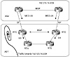
Figure 7-5 Policies inflicted
from outside sources.
Assume also that AS1 is very careful about injecting defaults. The SF
router will never inject a default if the SF link is down, and the NY
router will never inject a default if the NY link is down. All is well and
working great until one day provider AS2 starts advertising metrics (MED)
toward AS1.
Assume in figure 7-5 that AS2 is sending its updates toward AS1 with
the internal IGP metrics as MED. AS1 will receive the same networks on
both the SF and NY links with different MED values. For each network, BGP
will follow the path with the lowest metric. If, for example, RTC receives
network 192.213.16.0/24 with MED 50 on the SF link and MED 20 on the NY
link, RTC will prefer the NY link. This would mean that to reach
192.213.16.0/24, RTA might follow the interior default toward RTC and then
be instructed to go toward RTD. Similarly, RTB might follow a default
toward RTD and then be directed toward RTC. In both cases, a loop will
occur.
As you can see, the exit point for all networks cannot be predetermined
as in the primary/backup case. To deal with this situation, you have the
following options:
- • Ignore the MED and base the routing on a
primary/backup scenario.
- • Have a shorter path connection between RTC and
RTD so that traffic redirected between exit points follows the shortest
path between the IBGP routers.
- • Run an IBGP mesh between, RTA, RTB, RTC, and
RTD.
Other normal situations can also cause loops. You could end up in a
looping situation whenever you have multiple links and you are running
defaults inside the AS. If you are connected to two providers, you might
prefer some destinations via one provider and others via the second
provider. If your IGP is following defaults, you might end up at the wrong
exit point with no way to go back.
As you can see by now, the solution to solve looping problems is to
either have the BGP and your IGP be more deterministic about where to exit
the AS or prevent traffic between IBGP routers from going back over
IGP-only routers. The more you are aware of your traffic behavior, the
better you can avoid loop situations.
Policy Routing
Policy routing is a means of controlling routes that relies on
the source, or source and destination, of traffic rather than destination
alone. Policy routing can be used to control traffic inside an AS as well
as between ASs. Policy routing is a glorified form of static routing. It
is used when you want to force a routing behavior different from what the
dynamic routing protocols dictate.
Troubleshooting: Ch. 11, pp. 418-422. Policy Routing
Static routing enables you to direct traffic based on the traffic
destination. Traffic toward destination 1 can go via point A whereas
traffic toward destination 2 can go via point B.
Policy routing, on the other hand, enables you to direct traffic based
on traffic source or a combination of source and destination. Traffic
coming from network 1 can go via point A, or traffic coming from network 1
and going toward network 2 can go via point B.
Consider the example illustrated in figure 7-6. Assume that AS1 was
assigned network numbers from two different providers. The 10.10.10.0/24
range was taken from AS3, and the 11.11.11.0/24 range was taken from AS4.
AS1 wants to have any traffic originated from its 10.10.10.0/24 networks
to be directed toward AS3 and traffic from its 11.11.11.0/24 networks to
be directed to AS4, irrespective of the destination of the traffic. AS1
could use policy routing to achieve this requirement by forcing all
traffic with a source IP address belonging to 10.10.10.0/24 to have a next
hop of 1.1.1.1, and traffic with source IP belonging to 11.11.11.0/24 to
have a next hop of 2.2.2.2.
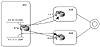
Figure 7-6 Policy routing
scenario based on source.
Policy routing can also be based on a source/destination combination.
This is illustrated in figure figure 7-7. Assume that RTA wants to use the
SF link for any traffic originating from network 10.10.10.0/24 and
reaching network 12.12.12.0/24 in NY. Also, RTA wants to use the SJ link
for any traffic originating from network 10.10.10.0/24 and reaching
network 13.13.13.0/24 in NY. Policy routing can be used to set the next
hop for the traffic combination (Source = 10.10.10.0/24, Destination =
12.12.12.0/24) to be 1.1.1.1. The traffic combination (Source =
10.10.10.0/24, Destination = 13.13.13.0/24) will be set with next hop
2.2.2.2.
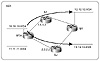
Figure 7-7 Policy routing
scenario based on source and destination.
Whenever static behavior is enforced, backup becomes an issue. It is
important to make sure that if policy routed traffic cannot be delivered
because the next hop is down, some other alternative is available. Cisco
offers a creative way of doing policy routing by offering multiple next
hops for policy routed traffic. If the first next hop is down or not
available, the second next hop will be tried, and so on. If none of the
statically defined next hops are available, the router can be configured
to send the traffic according to the normal dynamic routing (that is,
based on destination). This is illustrated in figure 7-8.

Figure 7-8 Policy routing
defaults to dynamic routing.
Other Applications of Policy Routing
One practical application of policy routing is its use with
firewalls. Firewalls are devices that apply security requirements
to traffic. Firewall implementations include packet filtering,
authentication, and encryption. Depending on the network setup,
administrators might want to direct some or all incoming (or outgoing)
traffic toward a firewall device (see figure 7-9).
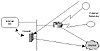
Figure 7-9 Incoming or outgoing
traffic can be routed to a firewall.
An applicable situation might involve traffic entering an organization
through dialup services. Perhaps the organization requires that the dialup
users from remote sites pass through a firewall before reaching the
Internet. If the firewall is in the traffic trajectory, this is not a
problem. Any inbound or outbound traffic will pass through the firewall on
its way to a destination. In some cases, however, (such as that shown in
figure 7-9), traffic bypasses the firewall in its normal path. Policy
routing can be configured on a router bordering external networks, to
force the incoming traffic to be directed to the firewall. After the
firewall applies its policies or encryption, traffic will be sent to its
destination.
Notes: Policy routing does not change the traffic
destination. It affects only the next hop to which traffic is directed
prior to being sent along toward its destination.
Policy routing can also be used with dialup services for better traffic
balancing, as illustrated in figure 7-10. Dialup users accessing a certain
point of presence can be directed toward certain providers based on their
source IP address. As illustrated in figure 7-10, dialup users in region 1
can be directed toward provider 1, whereas dialup users from region 2 can
be directed toward provider 2.
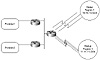
Figure 7-10 Balancing dialup
traffic based on source.
Policy routing should not replace dynamic routing, but instead should
complement it. Policy routing has its own set of drawbacks.
- 1. Extra configuration is needed to identify
sources of traffic or a combination of source and destination. Care
should be taken not to disrupt other traffic and to specify other
alternatives for traffic in case of backup situations.
- 2. Policy routing is CPU-intensive because it is
based on the source IP addresses, unlike dynamic and static routing,
which are based on the destination IP addresses. Sophisticated caching
and switching techniques have been implemented all along based on the
destination of the traffic. Most implementations have not yet optimized
routing and caching techniques based on the source of the IP packet. As
such, policy routing takes additional CPU cycles to detect source
addresses. This behavior should change as implementations move toward
better understanding of IP traffic flows that enable caches to keep
track of source and destination information. This new caching
methodology would alleviate routers from disruptive processing on
matching sources of IP traffic and make policy routing much more
effective and practical.
Looking Ahead
Autonomous systems can grow in size beyond administrators' control.
Service providers might find themselves with a large internal BGP mesh
that is both cumbersome and inefficient to control. On the other hand,
enterprise networks might grow in a manner that causes internal gateway
protocols to struggle in keeping up with instabilities. Controlling
large-scale autonomous systems lies in the art of dividing these large
domains into smaller and more manageable entities. The following chapter
offers concepts and techniques that can help providers and customers in
applying architectural designs to achieve structured routing inside their
domains.
Frequently Asked
Questions
Q— I am not running IBGP between my border routers; do
I have to worry about routing loops?
A— As far as the interaction between IGP and BGP, loops
cannot occur. If your internal routers are following a default
toward the BGP border routers, after the traffic reaches the border
router, it has only one way out via the EBGP session.
Q— I have two BGP border routers running IBGP and
connected via a serial link. I am using local preference to control
my exit points. What happens if the serial line goes down?
A— If you are setting BGP policies that cause traffic to
be directed between BGP routers, this would be the same scenario as
if you do not have a link between the border routers. While the
serial line is down, your traffic might end up looping inside the
AS.
Q— If I use a serial link between my IBGP border
routers to direct traffic from one router to the other, should that
link be as fast as my links to my providers?
A— The only traffic that line will carry is outbound
traffic that is redirected between border routers and a portion of
incoming traffic. Try to figure out what percentage of your total
traffic that constitutes to estimate the appropriate link
bandwidth.
Q— I need to direct traffic toward destination X over
my serial line and toward destination Y over my Ethernet line. Can I
do that via policy routing?
A— What you have just described can be done via static
routing, which works based on the basis of destination. There is no
need for policy routing, which works on the basis of source or
source and destination combined.
Q— Do I apply policy routing over my outbound or
inbound router interface?
A— Policy routing checks source addresses coming into an
interface. Configure on the inbound
interface. |
Previous
| Content |
Next


