Chapter 6. Redundancy, Symmetry, and Load
Balancing
This chapter covers the following key topics:
- • Redundancy
Building
stability by providing alternate—default—routes in case of link
failure is an important design goal of routing architecture.
- • Setting Default Routes
Configuring default routes is the fundamental method of
building redundancy into network connections. When multiple
default routes exist, methods of ranking them by preference are
needed.
- • Symmetry
Configuring routes
so that certain traffic enters and exits an AS at the same point
is usually a design goal of routing architecture.
- • Specific Scenarios
Exploration is offered of several representative network
designs with respect to developing redundancy, symmetry, and load
balancing. Examples of attribute configuration to achieve these
design goals for the different scenarios are offered.
Redundancy, symmetry, and load balancing are crucial issues
facing anyone implementing high-throughput connections to the
Internet. ISPs and corporations connected to ISPs require adequate
control over how traffic enters and exits their respective ASs.
Redundancy is achieved by providing multiple alternate
paths for the traffic, usually by having multiple connections to one
or more ASs. Symmetry means having traffic that leaves the AS
from a certain exit point return through the same point. Load
balancing is the capability to divide traffic optimally over
multiple links. Putting these three requirements together, you can
imagine how challenging it is to achieve an optimal routing
solution.
No single switch exists that you can turn on that gives you all
you need. On the Internet, multiple providers can control and
manipulate traffic that transits any AS. Any provider along the way
can direct the traffic. The art of balancing traffic depends on
coordination between multiple entities.
The general design problem of how best to implement redundancy,
symmetry, and load balancing is common to every network. The
specific answer, however, depends on the needs and configuration of
each particular network. This chapter considers the general design
problem within the context of several specific network
configurations. You might not see your exact network configuration
in these examples, but the general issues and implementation methods
they raise provide a model for your analysis and design of your own
routing needs.
Before examining specific network scenarios, it is necessary to
establish some basic concepts and definitions concerning
redundancy.
Redundancy
Although corporations and providers would prefer uninterrupted
connectivity, connectivity problems occur for one reason or another
from time to time. Connectivity is not the responsibility of one
entity. A router's connection to the Internet involves the router,
the CSU/DCU, cabling, physical access line, and numerous
administrators—each with influence over different parts of the
connection. At any time, the connectivity can be jeopardized by
human error, software errors, physical errors, or adverse unforeseen
conditions (such as bad weather or power outages).
For all these reasons, redundancy is generally desirable. But
finding the correct balance between redundancy and symmetry is
critical. Redundancy and symmetry can be conflicting design
goals—the more redundancy a network has, the more unpredictable the
traffic entrance and exit points would be. If a customer has
multiple connections—one to a Point Of Presence (POP) in San
Francisco and another to a POP in NY—traffic leaving San Francisco
might come back from NY. Adding a third connection to a POP in
Dallas makes connectivity even more reliable, but it also makes
traffic symmetry more challenging. These are the trade-offs that
network administrators must consider in implementing routing.
Geographical Restrictions
Pressure
In addition to the reliability motivation, companies might feel
geographical pressure to implement redundancy. Many contemporary
companies are national, international, or multinational in nature.
For them, the autonomous system is a logical entity that spans
different physical locations. A corporation with an AS that spans
several geographical points can take service from a single provider
or from different providers in different regions. In figure 6-1, the
San Francisco office of AS1 connects to the San Francisco POP of
ISP1, and the NY office connects to the NY POP of ISP2. In this
environment, traffic can take a shorter path to reach a destination
by traveling via the geographically adjacent POP.

Figure 6-1 Geographically
based multihoming situation.
Because redundancy refers to the existence of alternate routes to
and from a network, this translates into an additional number of
routing information that needs to be kept in the routing tables. To
avoid the extra routing overhead, default routing becomes an
alternate practical tool. Default can provide us with backup routes
in case primary connections fail. The next section attempts to
define the different aspects of default routing and how it can be
applied to achieve simple routing scenarios.
|
References
[1] RFC 1321 The MD5 Message-Digest Algorithm
[2] RFC 1997 BGP Communities Attribute
Setting Default Routes
Following defaults is a powerful technique in minimizing the amount of
routes a router has to learn and providing networks with redundancy in the
event of failures and connectivity interruptions. Cisco calls the default
path the gateway of last resort. It is important to understand how
default routing works, although it makes life easier when configured
correctly; life is more difficult when routing is configured
incorrectly.
By definition, a default route is a route in the IP forwarding
table that is used if a routing entry for a destination does not exist. In
other words, a default route is a last resort in case specific route
information for a destination is unknown.
Dynamically Learned Defaults
The universally known default route is usually represented by the
network mask combination 0.0.0.0/0.0.0.0 (also represented as 0/0). This
route can be exchanged as a dynamic advertisement between routers. Any
system advertising this route will be representing itself as a gateway of
last resort for other systems. Figure 6-2 illustrates such an
advertisement.
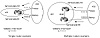
Figure 6-2 Dynamic default
advertisement.
Troubleshooting:
Ch. 11, pp. 368-373. Dynamically
Learned Defaults
Dynamic defaults (0/0) can be learned via BGP or via IGP, depending on
what protocol is running between two domains. For redundancy purposes and
to accommodate potential failures, you should be receiving defaults from
multiple sources. In the context of BGP, the local preference can be set
for the default to give a degree of preference over which default is
primary and which is backup. If one default goes away, the other will take
its place.
In the left instance of figure 6-2, a single router is connecting AS1
to AS2 via two connections. If AS1 chooses to accept as few routes as
possible from AS2, AS1 can accept only the 0/0 default route. In this
example, AS1 is learning 0/0 from two links and giving preference by
setting the local preference to 100 on the primary link and 50 (or any
number smaller than 100) on the backup link. This would set the gateway of
last resort to 1.1.1.1.
In the multiple routers scenario (right instance of figure 6-2), the
same behavior can be achieved with multiple routers as long as IBGP is
running inside the AS. Local preference, which is exchanged between
routers, will determine the primary and backup links.
Statically Set Defaults
It is also possible for an AS to statically set its own defaults by
setting its own 0/0 route. Statically set defaults provide more control
over routing behaviors because the operator has the option of defining his
last resort rather than it being forced on him by some outside entity.
Many operators choose to filter dynamically learned defaults to avoid
situations where traffic ends up where it is not supposed to be.
Troubleshooting:
Ch. 11, pp. 370-373. Statically
Set Defaults
An operator can statically set the default route 0/0 to point to the
following:
- • The IP address of the next hop gateway
- • A specific router interface
- • A network number
Figure 6-3 illustrates the first two possibilities. On the left, a
router is statically pointing its own 0/0 default toward the IP address
1.1.1.1. On the right, the same router is pointing its default toward an
Ethernet interface. In the latter approach, further processing is needed
to figure out to whom on the segment the traffic should be sent. Such
processing usually involves sending Address Resolution Protocol (ARP)
packets to identify the physical address of the next hop router.
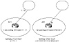
Figure 6-3 Statically set
defaults.
A system can also set its default based on some network number it
learns from another system. In figure 6-4, AS1 is dynamically learning
route 192.213.0.0/16 from AS2. If AS1 points its default to
192.213.0.0/16, that network will automatically become the gateway of last
resort. This approach uses recursive route lookup to find the IP address
of the next hop gateway. In this example, the recursive lookup will
determine that 192.213.0.0/16 was learned via the next hop 1.1.1.1, and
traffic would be directed accordingly.

Figure 6-4 Pointing default
toward a network number.
It is important for defaults to disappear dynamically if what they
point to disappears. Cisco enables a statically defined default to follow
the existence of the entity to which it is pointing. If the default, for
example, is pointing to a network number and that network is no longer
reachable (does not show in the IP routing table), the default will also
disappear from the IP routing table. This behavior is needed in situations
where multiple defaults exist. One default can be used as primary and
others as a backup in case the primary default is no longer valid.
Default networks should be selected as far upstream (closer to the
Internet) as possible so that they are more representative of the whole
link toward the NAP rather than a portion. This is important if the AS you
are connected to has a single connection toward the NAP. In figure 6-4,
AS1 can set the default toward its provider AS2 by pointing to prefix
128.213.11.0/24 or the supernet 192.213.0.0/16. Pointing the default to
128.213.11.0/24 makes it dependent on the stability of a portion of the
link (AS1 to AS2) and not the whole link (AS1 to AS3) toward the NAP. If
the link between AS2 and AS3 goes down, AS1 would be still sending traffic
toward AS2 rather than directing it to some other default (assuming that
AS1 has other providers). A better default choice would be the supernet,
192.213.0.0/16, because its existence is more representative of the whole
link toward the NAP and is no longer dependent on any intervening
links.
Troubleshooting:
Setting and selecting reliable
defaults.
Selected default networks should not be specific subnets. A subnet that
is flip-flopping might cause your default to come and go constantly. It is
much better to point the default to a major aggregate or supernet that
reflects the stability of a whole provider rather than a particular link.
Multiple static defaults can be used at the same time. One way to set
multiple static defaults is to point to multiple networks (use aggregates
if possible for stability reasons) and establish a degree of preference by
using the local preference attribute. This would apply to a single router
connected to the provider via multiple connections, or multiple routers
running IBGP inside the AS. Both scenarios are illustrated in figure 6-5.
These are similar to the scenarios you saw in figure 6-2, the only
difference being that the customer is setting its own default rather than
relying on the provider to send the 0/0 default route. In this example,
the customer will choose 128.213.0.0/16 with the local preference of 100
via the upper link. The lower link will be used as backup in case of
failure in the primary link.
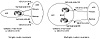
Figure 6-5 Statically pointing
to multiple networks defaults.
Another way of setting defaults statically involves using the Cisco
distance parameter (as described in Chapter 5, "Tuning BGP Capabilities,"
table 5-1) to establish a degree of preference. This would work only in
the case of one router connected to multiple connections because the
distance parameter is not exchanged between routers.
If two static default entries are defined with different distances, the
default with the lowest distance wins. If the better default goes away,
the second default becomes available. If both defaults have the same
distance, then traffic will be balanced between the two defaults.
Figure 6-6 illustrates the use of the distance parameter in setting
multiple defaults. AS1 is connected to AS2 via two links and is setting
its own defaults toward AS2. AS1 uses one link as primary by giving the
static default a distance of 50, lower than the distance of 60 given to
the backup link. In case of failure in the primary link, traffic will
shift toward the backup.
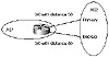
Figure 6-6 Static defaults
pointing to multiple connections.
Symmetry
Symmetry refers to the fact that traffic leaving the AS from an exit
point comes back through the same point. This is easy to achieve if a
single exit and entrance point exists. But, given the mandates of
redundancy and the presence of multiple connections, traffic tends to be
asymmetrical. When it is, customers and providers notice a lack of control
over how traffic flows in and out of their ASs. Traffic leaving the AS
from the East Coast might end up taking the "scenic route," coming back
from the West Coast and traveling inside the AS multiple hops before
returning to its origin.
Actually this is not as bad as it sounds, and in some situations
asymmetrical traffic is acceptable depending on the overall physical
topology as far as the speed of the links and the number of hops between
locations. In general, customers and providers would like to see their
traffic come back close to or at the same point it left the AS to minimize
potential delays that could be incurred otherwise.
To accommodate symmetry, a primary link should be chosen, and a best
effort should be made to enable the majority of traffic to flow on this
link. Redundancy would be accommodated by enabling other links to be
backup links that will be used if the primary link is problematic.
Load Balancing
Load balancing deals with the capability to divide data traffic over
multiple connections. A common misconception about balancing is that it
means an equal distribution of the load. Perfectly equal distribution of
traffic is elusive enough even in situations where traffic flows in a
network that is under a single administration. Given the multiple players
that traffic has to touch, equal distribution of the traffic is difficult
to achieve in most scenarios. Load balancing tries to achieve a traffic
distribution pattern that will best utilize the multiple links that are
providing redundancy. To achieve this requires a good understanding of
what traffic you are trying to balance, incoming or outgoing.
It is important not to think about traffic as a single entity. Traffic
is two separate entities, inbound and outbound. With respect to an
autonomous system, inbound traffic is received from other ASs, whereas
outbound traffic is sent to other ASs.
Suppose that you are connected to two ISPs and traffic is overloading
your link to ISP1. Your question should be: What traffic—inbound or
outbound? Are you receiving all your traffic from ISP1, or are you
sending all your traffic toward ISP1?
The patterns of inbound and outbound traffic go hand in hand with the
way you advertise your routes and the way you learn routes from other ASs.
Inbound traffic is affected by how the AS advertises its networks to the
outside world, whereas outbound traffic is affected by the routing updates
coming in from outside ASs. Make sure that you fully understand this
behavior because it will be the basis of all future discussions. From now
on, whenever we talk about taking steps to affect inbound traffic, we are
really talking about applying attributes to outbound routing announcements
because how our routes are learned by others affects how traffic is routed
inbound. Similarly, whenever we talk about taking steps to affect outbound
traffic, we are talking about applying attributes to inbound routing
announcements, because how our network learns routes affects how outbound
traffic is routed.
Figure 6-7 illustrates how inbound and outbound traffic behaves. As you
can see, the path for outbound traffic to reach NetA depends on where NetA
is learned from. Because NetA is received from both SF and NY, your
outbound traffic toward NetA can go via SF or NY.
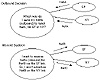
Figure 6-7 Inbound and outbound
decisions.
On the other hand, the path for inbound traffic to reach your local
networks, NetB and NetC, depends on how you advertise these networks. If
you advertise NetC over the NY link only, then incoming traffic toward
NetC will take the NY link. Similarly, if you advertise NetB over the SF
link only, traffic toward NetB will take the SF link.
Specific Scenarios: Designing
Redundancy, Symmetry, and Load Balancing
By now you recognize the general ways in which the design goals of
redundancy, symmetry, and load balancing intersect with and potentially
conflict with one another. How is it possible to balance traffic among
multiple links and still achieve a single entrance and exit point as
symmetry mandates? This becomes even harder when multiple links are spread
out over multiple routers in the autonomous system. The routing attributes
described in Chapter 5, "Tuning BGP Capabilities," are the tools for
implementing the desired redundancy, symmetry, and load balancing. It is
the responsibility of the operator to choose and configure the correct
attributes and filtering to achieve the desired outcome.
This section presents specific scenarios and attempts to configure them
in such a way as to optimize redundancy, symmetry, and load balancing. The
scenarios are not representative of every possible network configuration,
and the design solutions shown here are not the only ones possible. But
the lessons they illustrate can be applied to other scenarios and will
help you understand and implement better and more efficient designs.
The first scenario is a simple case followed by increasingly complex
scenarios. Note that there is a fine line between a customer and provider
in many cases because a provider can be the customer of another provider.
The principal distinction is this: customers obtain Internet connectivity
by connecting to providers, but do not themselves offer connectivity to
other customers. Providers offer Internet connectivity services and can
themselves be customers of other providers.
The scenarios to be considered in the following subsections are further
divided depending on whether the customer is receiving minimal or no
routes, partial routes, full routes, or some combination of these from the
providers. In the case where the customer is accepting minimal or no
routes (called default only), you can assume that the customer can still
learn the 0/0 route or a couple of aggregate routes that enables him to
statically set a default. Partial routing usually consists of the
provider's local routes and the provider's other customers' routes.
Full routing means all Internet routes in existence—about 42,000
routes in 1996. A combination of these scenarios can occur where a
customer can receive a default route and partial routes from the same
provider, or partial routes from one provider and full routes from another
and so on.
Scenario 1: Single-Homing
Single-homed customers have sites that connect to the Internet via a
single connection to a service provider. Figure 6-8 illustrates such a
situation. These customers can usually be adequately served by pointing
defaults toward the provider. The provider can also install static routing
to reach the customer. This method is the least expensive and the most
effective. The customer router does not need to learn any of the Internet
routes. This substantially reduces memory usage and processing overhead.
In this case, there is no issue of route symmetry because traffic has a
single entrance and exit point.

Figure 6-8 Simple single-homed
site situation.
Single-homed sites generally rely on a single connection to the
Internet. Backup is not an issue. If the connection is lost, the customer
can tolerate the outage until it is fixed. Obviously, such an arrangement
would not satisfy mission-critical data communication requirements. A
single-homed site with no backup access would not be appropriate for
applications needing high levels of reliability.
Scenario 2: Multihoming to a Single
Provider
A customer with multiple connections to the Internet via the same
provider is considered to be multihomed to a single provider. For
multihoming to a single provider, assume that BGP is used as a routing
protocol. Although it is not necessary in all cases, it is recommended.
Default Only, One Primary, and One Backup
Link
In this scenario, the customer configures default routing toward the
provider and is not accepting partial or full routes. The customer can run
default to both connections. In figure 6-9, the customer wants to use one
link as the primary traffic conduit and the other as a backup in case the
primary link goes down. (If there were more than two connections to the
provider, the customer could set up multiple defaults with varying
preference levels.)

Figure 6-9 Basic
mulithoming/single provider scenario.
Troubleshooting:
Ch. 11, pp. 373-376. Default
Only, One Primary, and One Backup Link
Customer's Outbound Traffic
In the scenario of figure 6-9, where a single router is used to connect
to the provider in multiple locations, multiple static defaults with
different distance values can be used, as already discussed in figure 6-6.
The default with the lower distance will be the primary. The 0/0 default
route or few aggregate routes can also be learned dynamically from the
provider to enable the customer to set the default. Local preference can
be used to prefer one default over the other.
Assume in figure 6-9 that the default to NY is more preferred than the
default to SF. In normal operations, the customer will use the NY link as
the primary link and the SF link as a backup.
For outbound traffic, load balancing is not an option because all
traffic is sent over the primary line, and the secondary is kept as
backup.
Absence of load balancing is offset by the fact that the customer's
router requires less memory and processing power.
Customer's Inbound Traffic
The customer can advertise its networks to the provider via BGP. The
provider will have two paths to reach the customer. Which path it chooses
affects the customer's inbound traffic. Usually, the provider's default
behavior (assuming that all attributes are the same) is for traffic to
flow back to the customer's AS depending on which of the provider's exit
points it is closest to. If traffic toward the customer is closer to the
NY link, then it will enter the customer's AS via NY. If it is closer to
SF, then it will enter via SF.
All the previous factors are outside the customer's control. Customers
who want to override these influences and control incoming traffic via one
path or the other can do so by advertising their routes with different
metrics. The provider will direct its traffic toward the customer based on
the metric value. In figure 6-9, the customer is advertising its routes
with a metric of 50 toward NY and a metric of 100 toward SF. As such,
traffic toward the customer will take the NY route.
Default, Primary, and Backup Plus Partial
Routing
This is the same scenario as the default, primary, and backup case
except that the customer can accept partial routing from the provider.
Figure 6-10 illustrates this environment. This approach gives the customer
better flexibility in choosing its exit point because more routing
information is provided. As previously, both inbound and outbound traffic
patterns are discussed.
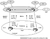
Figure 6-10 Multihoming/single
provider scenario with partial routing.
Troubleshooting:
Ch. 11, pp. 376-382. Default,
Primary, and Backup Plus Partial Routing
Customer's Outbound Traffic
Consider a situation in which customer 1 is connected to the provider
via two separate routers. The customer has the option of deciding which
path to take for each of the partial routes it accepts from the provider.
This is usually done by setting different local preference for different
routes coming into the customer's AS. Local preference can be set on an
AS_path or prefix basis or both. If set based on an AS_path, then the
local preference will apply to all prefixes contained in a particular AS.
In case routing decisions need to be made on a prefix basis, the local
preference can be set based on each prefix. In figure 6-10, based on the
physical location of certain ASs or prefixes, the customer can choose to
forward traffic to customer 2 and customer 3 (C2 and C3) on the SF link
and to C4 and C5 on the NY link. The customer can achieve this by doing
the following:
- • For routes being learned on the NY link, assign
a local preference of 300 for the C4 and C5 routes. Give all other
routes a preference of 250 (this would include C2 and C3).
- • For routes being learned on the SF link, assign
a local preference of 300 for the C2 and C3 routes. Give all other
routes a preference of 200 (this would include C4 and C5).
When presented with multiple routes for the same destination (via
external and internal BGP), the customer will prefer the C4 and C5 routes
via the NY link (300 > 200). In the same manner, the customer will
prefer the C2 and C3 routes via the SF link (300 > 250). For customers
other than C2, C3, C4, and C5, the NY link will be preferred (250 >
200).
For all other Internet routes not known to customer 1, default will be
taken in the primary backup manner. The 0/0 default route could be
dynamically learned from the provider from both ends, or could be
statically configured to point to one of the provider's networks (as
discussed in the "Setting Default Routes" section of this chapter). Local
preference could be used to prefer one default over the other. Based on
the way the local preference routes for the C2, C3, C4, and C5 customers
were set, all other routes including the 0/0 will be preferred via the NY
link (250 > 200).
A totally different approach that doesn't require as much configuration
on the customer's side is for the provider to send its metrics toward the
customer. This option was discussed in the MED section of Chapter 5. If
metrics coming from the provider are representative of how close or how
far networks are from the entrance points to the customer networks, then
the customer will be able to load balance its outbound traffic
accordingly. Traffic toward C4 and C5 will go out on the NY link, and
traffic toward C2 and C3 will go out on the SF link. Other traffic will
flow depending on what metrics are associated with the routes learned on
each link. Although this method requires less configuration, it is also
less deterministic on the customer's side because its traffic trajectory
is totally dependent on the provider's setup. A combination of both
approaches discussed might give the best behavior.
Customer's Inbound Traffic
The customer can influence inbound traffic by advertising different
metrics on different links. Some providers encourage their customers to
send their internal IGP metrics as BGP metrics (also discussed in Chapter
5). This way, the provider will deliver traffic to the customer via the
link closer to the destination. In the example illustrated in figure 6-10,
the customer has decided to manually set the metrics to force the
following behavior:
- • For routes being sent on the NY link, send the Z
and W prefixes with a MED of 200. Give all other prefixes a metric of
250. (This includes X and Y.)
- • For routes being sent on the SF link, send the X
and Y prefixes with an MED of 200. Give all other prefixes a metric of
300. (This includes Z and W.)
When presented with multiple routes for the same destinations, the
provider will access the Z and W prefixes over the NY link (200 < 300).
In the same manner, the provider will access the X and Y prefixes over the
SF link (200 < 250). For all prefixes other than X, Y, W, and Z, the
provider will choose the NY link (250 < 300).
Default, Primary and Backup, Full and Partial
Routing
For customers multihomed to a single provider, the customer can either
get full routes on all its connections to the provider, or the customer
can have a combination of full routes on one link and no routes (default)
or partial routes on the other links. The same techniques discussed in the
preceding sections would apply here: local preference is used to control
the customer's outbound traffic, and the metric is used to control the
inbound traffic. Also, if internal metrics are exchanged between customer
and provider, a certain level of load balancing can be achieved.
Note:
Careful! When dealing with outbound traffic,
manipulating exit points for specific routes is dangerous. Routing loops
can occur if outbound traffic following an IGP default toward the
customer's BGP router gets directed toward another router following
default to the BGP router. This situation might seem confusing now, but
will become more clear in the next chapter.
Automatic Load Balancing
As is probably clear from the previous scenarios, load balancing is
not a very intuitive task and requires extensive planning. To help,
Cisco IOS software supports dynamic load balancing for identical
destinations learned via EBGP by the same router and coming from the
same autonomous system. This will reduce configuration efforts.
Troubleshooting:
Ch. 11, pp. 382-385. Automatic
Load Balancing
Figure 6-11 illustrates an example in which the same router (NY) is
connected to its provider via two links and is getting identical routing
on both links. A Cisco router will keep in its IP routing table up to
six identical BGP routes to the same destination. When passing on the
EBGP updates to the IBGP peers, however, the router will only pass on
one best route. The next hop address of the route will automatically be
changed to reflect the router's (NY) own IP address instead of having
the EBGP next hop address carried into IBGP. Note that this is done
automatically only in the case where load balancing is configured
dynamically.
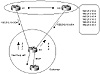
Figure 6-11 Router receiving
identical routes from two sources.
By default, a Cisco router will load balance on a per destination
(Host) basis. Balancing on a destination basis is done in round-robin
fashion. One host will be locked to one path, the next host will be
locked to the other path, and so on.
Figure 6-11 assumes that the customer is getting two identical routes
to network 192.213.10.0/24. Without automatic load balancing, the BGP
process prefers one path only. It is up to the administrator to try to
affect the BGP decision by changing attributes to balance the traffic
between paths.
With automatic balancing, BGP will keep two entries for the
192.213.10.0/24 prefix, one via the SF link and one via the NY link.
Outbound traffic from the customer network will then be split over the
two links on a round-robin basis, assuming that the customer needs to
send traffic to the destinations 192.213.10.1 to 192.213.10.6.
Destination 10.1 will be reached via the SF link, destination 10.2 will
go over the NY link, destination 10.3 will go over the SF link, and so
on.
Note:
Load balancing in this manner works only
when dealing with identical routing updates coming into the same
router from the same provider. This method does not work to load
balance in a multiprovider environment.
In the example illustrated in figure 6-11, automatic load balancing
works well for outbound traffic. For inbound traffic, you must resort to
manipulating metrics to influence the provider's decision.
Balancing Between Two Routers Sharing Multiple
Paths
In some situations, two routers share multiple physical paths for
backup or higher bandwidth services, as illustrated in figure 6-12.

Figure 6-12 Load balancing
between two routers sharing multiple paths.
To balance traffic in this environment, one option is to implement
dynamic balancing. This is simply a special situation of the previous
automatic load balancing case. Dynamic load balancing, however, will
result in extra overhead for the routers. Each router would receive
duplicate update messages from the other router. In the case of full
routing, the result would be approximately 42,000 routes arriving on
each link. Instead, it is possible (and preferable) to achieve load
balancing for the situation illustrated in figure 6-12 by using a static
approach.
In the normal behavior, BGP keeps the best next hop for each prefix
it learns. As seen in table 6-1, RTA will receive two identical BGP
routes for NetX. BGP will pick the best route and install it in its IP
routing table. In this case, BGP has picked the route via next hop
10.10.10.2. Table 6-2 illustrates RTA's IP routing table where the next
hop 10.10.10.2 is reachable via link1. As a result of this
configuration, traffic toward networks learned from RTB will be sent
over link1. Hence, no load balancing is achieved.
Table 6-1 RTA's BGP table— NetX reachable
via 10.10.10.2.
|
| Destination
| Next Hop
|
|
| NetX
| 10.10.10.2 (best)
|
| NetX
| 11.11.11.2
|
|
Table 6-2 RTA's IP routing table —NetX
reachable via Link1.
|
| Destination
| Next Hop
|
|
| NetX
| 10.10.10.2
|
| 10.10.10.0/24
| Link1
|
|
Troubleshooting:
Ch. 11, pp. 385-387. Balancing
Between Two Routers Sharing Multiple Paths
BGP can be fooled by setting the next hop to a virtual interface
rather than the physical link and by using the IP routing table to do
the actual load balancing.In figure 6-13, RTB can be assigned a loopback
interface (virtual interface), and RTA can use that address to set up
the BGP neighbor connection. This way, the loopback interface itself and
not the IP address of the physical link will be used as a next hop. Some
dynamic IGP or static routing can be used to load balance between the
links independent of BGP.

Figure 6-13 A single BGP
session across multiple physical links.
As seen in table 6-3, RTA will receive its BGP routes from its
neighbor 12.12.12.12 and will be able to reach NetX via the next hop
12.12.12.12. Table 6-4 illustrates RTA's IP routing table. Next hop
12.12.12.12 can be reached via link1 and link2. Reachability of the
12.12.12.0/24 network can be achieved via IGP or by pointing multiple
static routes toward link1 and link2. The router can now load balance
the traffic. Due to the recursive route lookup in this scenario, load
balancing is done per network rather than per destinations. Networks
learned from RTB can now be reached round robin over multiple links.
Table 6-3 RTA's BGP table— NetX reachable
via 12.12.12.12.
|
| Destination
| Next Hop
|
|
| NetX
| 12.12.12.12
|
|
Table 6-4 RTA's IP routing table — NetX
eachable via Link1 or Link2.
|
| Destination
| Next Hop
|
|
| NetX
| 12.12.12.12
|
| 12.12.12.0/24
| Link1
|
| 12.12.12.0/24
| Link2
|
|
Scenario 3: Multihoming to Different
Providers
A customer connected to multiple providers is considered to be
multihomed to different providers. Redundancy and geographical
restrictions are strong motivations for multihoming. The outbound
traffic behavior for each iteration of this scenario will be considered
on a case-by-case basis. For all cases, the inbound traffic behavior is
the same and is covered at the end of the section.
Default Only, Primary and
Backup
In this case, the customer can follow defaults toward the provider.
One link will be used as primary, and the second link as backup. Figure
6-14 illustrates a relevant situation.
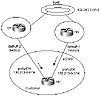
Figure 6-14 Multihoming to
two providers.
A customer can set the default routes to the two providers statically
or can dynamically learn 0/0 from both providers. The customer can
prefer one default over another by using the "distance" or local
preference. One good method of pointing defaults to both providers is to
accept the same network from both providers. The customer will configure
its 0/0 default based on that network and can manipulate local
preference to choose one link over the other. In case one default goes
away because of a link failure toward one provider, the other default
will take its place. The customer can either negotiate with the
providers to send him only the one network entry, or the customer can
filter all updates on his end except for the one entry.
In Figure 6-14, the customer is pointing the default toward the
prefix 192.213.0.0/16 it is receiving from both providers and setting
the local preference on the NY link to be higher (200). The NY link will
be the primary link, and the SF link will be the backup.
Default, Primary, and Backup Plus Partial
Routing
The addition of partial routing to the environment introduced in the
previous discussion changes the traffic behavior. Figure 6-15
illustrates the new situation. The customer can accept partial routing
from one or both providers and run default toward both providers with
one default preferred over the other.
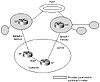
Figure 6-15 Multimihoming to
two providers plus partial routing.
By accepting partial routing from the providers, a customer does not
need to see all Internet routes and can still make a best route decision
when routing toward its direct providers. (For some major providers,
partial routes could represent a substantial number of routes.) In the
case illustrated in figure 6-15, BGP will make the right choice, and the
customer will choose the provider link closest to the destination
network (shorter AS_path). For other Internet routes, the basic
principal of primary and backup can be used. The customer can point to a
specific network to be the default, accept that network from both
providers, and use local preference to prefer one link over the other.
Default, Primary and Backup, Full and Partial
Routing
In multihoming to different providers, accepting full routes from
both or either providers is not really necessary unless the customer
plans to be a provider itself and pass along full routes to its
customers (act as a transit AS). Figure 6-16 illustrates a relevant
environment.
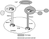
Figure 6-16 Multimihoming to
two providers with full and partial routing.
Troubleshooting:
Ch. 11, pp. 387-392.
Multihoming to Different Providers
The customer can accept full routing from one or both providers
depending on how much load balancing he wants to do. In the case of full
routing from both (or multiple) providers, the customer can use local
preference to decide which networks can be accessed via which provider.
Decisions can be made based on AS or prefix information. In some cases,
the customer might want to accept full routing from one provider and
just do partial/default routing with the other provider. This way, the
customer can get the best of both worlds without having to deal with
managing full routes from different links. As you will see later,
Internet instabilities caused by any provider could cause routers to
become very CPU-intensive.
In figure 6-16, the customer is receiving full routes from the NY
provider and partial routes from the SF provider. The customer is also
pointing a default toward the SF provider. For the SF local and customer
routes, the SF link will be used because of the shorter AS_path. For all
other routes, the NY link will be used because the SF link is only
providing partial routes. In case the SF link goes down, all networks
can be reached via NY. In case the NY link goes down, the customer can
still reach all Internet routes by following a default toward the SF
link.
Customer Inbound Traffic (AS_Path
Manipulation)
The inbound traffic is affected by how the customer advertises its
networks to the providers. Note that with the multiprovider scenario,
sending different metrics from the customer's end will not have any
effect. This is because the MED is always terminated at the provider's
network and is not carried to the other provider.
To affect the providers' behavior dynamically, the customer can
manipulate the AS_path attribute by inserting bogus entries in the
AS_path to affect the AS_path length. The providers will receive the
same prefix information with different path length and will pick the
path with the shortest length. Note that in a multiprovider environment,
it is not enough to influence the direct provider only because there is
no guarantee that the direct provider will get the traffic itself. Path
manipulation will have to influence providers all the way up to the NAP
because this is where the balance (as far as path length) will be tipped
one way or the other.
Figure 6-17 illustrates how bogus entries in the AS_path affect
routing. The customer (AS100) has inserted a bogus entry (100) in its
AS_path toward AS300. Providers at the NAP will get the same prefixes
with different path length (300 100 100 versus 200 100) and will pick
the shorter path via AS200. The bogus entry should be a repeat of the AS
that originated the entry (in this case 100).
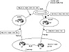
Figure 6-17 Using bogus
AS_path entries to affect routing.
Scenario 5: Customers of Different Providers with a
Backup Link
It is not unusual for separate ASs to require Internet
interconnection and to have different Internet service providers.
Whenever multiple providers are involved and the customers of these
providers agree to back up one another, support can get complicated.
This section takes the previous discussions one step further and
discusses how this backup connectivity is addressed from the provider's
point of view.
Troubleshooting:
Ch. 11, pp. 394-399. Customers
of Different Providers with a Backup Link
In figure 6-20, AS1 is the customer of ISP1, and AS2 is the customer
of ISP2. AS1 and AS2 have also entered a bilateral agreement under which
the private link between the two ASs will be used as a backup in the
event of a failure of either primary Internet link. Normally, an
individual AS does not want to be used as transit for another AS. In the
case illustrated in figure 6-20, AS1 wants ISP1 to set its routing
configuration so that ISP1 reaches AS2 via ISP2. Similarly, AS2 would
prefer ISP2 to set its routing configuration so that ISP2 reaches AS1
via ISP1. In this scenario, for the backup link to work, AS1 advertises
AS2's networks to ISP1, and AS2 advertises AS1's networks to ISP2.
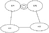
Figure 6-20 Customers of
multiple providers with a backup link.
The discussions about primary and backup are the same as with the
scenario discussed in the preceding section, "Scenario 4: Customers of
the Same Provider with a Backup Link." The private link can be a pure
backup or can be used for interior traffic between customers.
The requirement to have the provider not use one customer to reach
the other customer is more complicated. ISP1 will have to set the local
preference for AS2 routes coming from ISP2 to be higher than the routes
coming from AS1.This would cause ISP2 to be used under normal
operational conditions. The same strategy might be deployed for
ISP2.
Providers, however, would like to minimize configuration on their end
as much as possible. In cases where a provider has multiple customers
coming online every day, tracking the local preference for each can be
cumbersome. Providers would also like to set their policies based on AS
numbers rather than specific networks.
A couple of approaches can be used to implement the required
policies. The first approach is the community approach, which requires
coordination between providers and their customers. The second approach
is the AS_path manipulation approach. AS_path manipulation is easier to
implement, but might not be available in all vendor products.
The Community Approach
The use of the community attribute becomes very effective. Providers
want to map certain community values to corresponding local preference
values. Routing updates coming from customers having a specific
community will automatically be given the corresponding local
preference.
Troubleshooting:
Ch. 11, pp. 394-399. Customers
of Different Providers with a Backup Link
To keep this scenario manageable, only routing and policy setting
from ISP1's point of view is addressed. An identical discussion would
apply to ISP2. Traffic flow for the case figure 6-21 illustrated in can
be divided into a minimum of three patterns.
![]()
Figure 6-21 See Community
approach solution.
Note:
There can be more flow patterns, depending
on how many connections a customer has to its provider, but the basic
set of three illustrates required considerations.
Flow patterns from ISP1's point of view can be summarized as follows:
- • Pattern 1—Routes originated by the
customer AS1, or customer local routes.
- • Pattern 2—Routes transiting via AS1.
These routes come from AS2 and consist of AS2's routes and all other
routes that AS2 is receiving from ISP2. ISP1 uses this information to
reach AS2 via AS1 as a backup in the event that AS2's link to ISP2
fails. This pattern is referred to as customer transit routes.
- • Pattern 3—All other routes coming from
ISP2, or ISP routes. These can include routes learned from AS2.
Having divided the routes into different categories, ISP1 will assign
a community value to each pattern and will dynamically map it to the
local preference, as listed in table 6-5.
Table 6-5 Dynamic mapping of local
preference.
|
| Pattern
| Community
| Local Preference
|
|
| Customer local routes
| none
| 100
|
| Customer transit routes
| 400:40
| 40
|
| ISP routes
| 400:60
| 60
|
|
ISP1 will inform all its customers and connected ISPs that its local
preference values are dynamically set according to Table 6-5. Customers
can then dynamically influence the ISP's decision by sending the
corresponding community values. In the example illustrated in figure
6-21, AS1 will send its local routes with no community and the transit
routes with community 400:40. ISP2 will send its routes with community
400:60.
According to the preferences summarized in table 6-5, ISP1 prefers
AS1's local routes via its direct link to AS1 (preference 100 is the
highest). ISP1 prefers all other routes, including AS2 routes, via ISP2
(preference 60 is higher than 40.)
The AS_Path Approach
The AS_path manipulation approach is the same as was discussed for
multihoming to different providers, under "Customer Inbound Traffic
(AS_Path Manipulation)." It is straightforward and has proven to be one
of the the most efficient methods of influencing a provider's routing
decisions. Figure 6-22 illustrates an environment in which AS_path
manipulation is used to direct routing processes.

Figure 6-22 AS_path
manipulation example.
Troubleshooting:
Ch. 11, pp. 398-399. The
AS_Path Approach
For the case illustrated in figure 6-22>, assume that all local
preference attributes are kept at their default values to avoid
overriding the AS_path attribute. With this assumption in mind, ISP1
will use the direct link to AS1 for AS1's local traffic and the direct
link to ISP2 to reach ISP2's traffic. This is done based on the shorter
AS_path.
For traffic going to AS2, ISP1 has an equal path via ISP2 and AS1.
ISP1's AS_path to AS2 via AS1 is 1 2 and the AS_path via ISP2 is 500 2,
which are of equivalent length.
To influence ISP1's decision, AS1 must increase the AS_path length
when advertising AS2's routes to ISP1 by prepending an additional AS
number to the AS_path list. Normally, AS1 will repeat its own AS number.
ISP1's new AS_path to reach AS2 via AS1 will be 1 1 2, which is longer
than ISP1's AS_path to reach AS2 via ISP2 500 2. As a result, ISP1 will
use ISP2 to reach AS2.
Looking Ahead
Mastering routing at the edges of your domain gives you full control
over traffic in and out of your autonomous system. Still, another piece
of the puzzle is how the traffic flows inside the AS before it gets out.
Not all routers inside the AS run BGP. IGP-only routers usually do not
carry a full list of Internet routes due to memory constraints. Running
defaults inside the AS to reach external routes is one of the most
common ways for internal routers to reach destinations outside the AS.
With defaults comes the threat of routing loops if conflicting policies
exist between your BGP and your IGP. The following chapter discusses
these issues of how to make BGP policies flow hand-in-hand with IGP
defaults. The chapter also discusses the use of policy routing in
achieving total control over routing behaviors based on the sources of
IP addresses rather than the traditional destination-based routing.
Frequently Asked
Questions
Q—I statically defined a default toward my provider
by pointing toward a network I am learning via BGP. What
happens if that network goes up and down?
A—Your default will appear and disappear. That is why
you should not point your default to a specific subnet. Always
point to an aggregate or supernet because they are less likely to
flip-flop.
Q—I have the option of getting the 0/0 default via
BGP or defining a static default. What do you think is
best?
A—For the border router, both methods are the same as
long as the aggregate you are pointing to is stable. On the other
hand, after you receive the 0/0 via BGP, it will get flooded to
all your IBGP peers and there is a chance that you will end up
sending it out to your other EBGP peers. When you define the
default statically, you will have better control.
Q—I need to have a primary link where all my traffic
flows and a backup link in case of failure. I also need to load
balance my traffic. Is that possible?
A—That is not possible. If you are using your primary
link for all inbound and outbound traffic, this would dictate that
no other traffic will flow on the other link. These are two
contradicting requirements.
Q—My AS is connected to two providers, one
in SF and one in NY. I want the traffic from and toward
my SJ site to go in and out on the SF link. All other traffic
should flow over the NY link. What do I need to do to achieve this
behavior?
A—For your inbound traffic toward San Jose, you can use
the AS_path manipulation technique to make your path longer for
all SJ routes advertised on the NY link. The problem is with your
outbound traffic. If you know exactly what networks the SJ users
are trying to reach, you can give those destinations better local
preference on the SF exit. If the SJ site needs to reach any
destination, then setting a better local preference on the SF link
will cause all your outbound traffic to leave via the SF link.
That doesn't meet your requirement about the NY link carrying all
other traffic.
Another way of dealing with this scenario is policy routing,
where a router can track source addresses and direct traffic
accordingly. This is described in Chapter 7, "Controlling Routing
Inside the Autonomous System."
Q—I am prepending AS numbers to my routes to tip the
balance of my traffic. I am not seeing any effect. Why?
A—Remember that your updates are exchanged by multiple
providers. A provider along the way can use local preference to
override your path length. Check with your provider.
Q—Do I have to set BGP policies? Why can't I leave it to
BGP to figure out the correct path?
A—You do not have to set policies. Remember, though,
that BGP is not taking into account the speed of your links and
your user traffic requirements. If you are happy with your traffic
pattern the way it is, then you do not need to change any
attributes.
Previous
| Content
| Next
|


