Chapter 8. Controlling Large-Scale Autonomous
Systems
This chapter covers the following key topics:
- • Route Reflectors
A method of
managing expanding mesh requirements in large ASs by using
selected routers as focal points for internal BGP sessions
- • Confederations
A method of
managing expanding mesh requirements in large ASs by creating
sub-ASs
- • Controlling IGP Expansion
Methods of managing networks in which expansion is
characterized by the use of multiple IGPs
- • Virtual Private Networks with Route
Reflectors
A method of developing restricted network
access, within an AS, using route reflectors
Autonomous systems consisting of hundreds of routing nodes can
pose a serious routing management problem for network
administrators. Service providers and customers each have their own
set of problems when dealing with large networks. On the service
provider side, the majority of routers run BGP. The IBGP mesh will
grow beyond the provider's control. On the customer side, however,
the majority of routers run IGPs, which also may grow beyond the
customer's control.
This chapter discusses methods and techniques that can be used to
better control the deployment of BGP and IGPs inside large
autonomous systems. There are no absolute rules that say a provider
or customer should or should not use one of the methods discussed in
this chapter, or which method to prefer. Keep in mind that any new
technique brings with it its own complexities. Imposing complex
techniques on situations that do not really need them could hurt
more than help.
Route
Reflectors
In some ISP networks, the internal BGP mesh becomes quite large
(more than 100 internal BGP sessions per router), which strongly
suggests that some new peering mechanism be implemented. The
route reflector [1] concept is based on the idea of
specifying a concentration router to act as a focal point for
internal BGP sessions. Multiple BGP routers can peer with a central
point (the route reflector), and then multiple route reflectors peer
together.
Route reflectors are only recommended for ASs with a large
internal BGP mesh, on the order of more than 100 sessions per
router. The route reflector concept introduces processing overhead
on the concentration router and, if configured incorrectly, can
cause routing loops and routing instability. As a result, route
reflectors are not recommended for every topology. If it can be
tolerated, a full mesh is the better solution.
Troubleshooting:
Ch. 11, pp. 422-426. Route
Reflectors
Internal Peers Without Route
Reflectors
Without route reflectors, BGP speakers in an AS will have to be
fully meshed. We have already discussed this behavior in this book;
the following illustration is just a reminder. In figure 8-1, RTA,
RTB, and RTC form an internal BGP full mesh. Each router acts as a
BGP peer with the other two routers. RTA and RTB are physically
connected, as are RTB and RTC. No physical connection exists between
RTA and RTC.
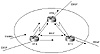
Figure 8-1 Internal peers
in mesh environment.
RTA gets an update from an external peer and will pass it on to
its two internal peers, RTB and RTC. Note that even though there is
no physical connectivity between RTA and RTC, RTA will manage to
pass the update to RTC via the BGP peering session. RTB and RTC, in
turn, will pass on the update to their external peers.
RTB will not pass on the update to RTC, because RTC is an
internal peer and the update received by RTB also comes from an
internal peer. Without the internal BGP session between RTA and RTC,
RTC would never get the update; hence, the full mesh is
necessary.
Internal Peers with Route
Reflectors
The route reflector acts as a concentration point for other
routers called clients. The clients peer with the route
reflector and exchange routing information with it. In turn, the
route reflector will pass on (reflect) the information between
clients.
In figure 8-2, RTA gets an update from an external peer and
passes it on to RTB. RTB is configured as a route reflector with two
clients, RTA and RTC. RTB will reflect the update from client RTA to
client RTC. In this configuration, a peering session between RTA and
RTC is not really needed because the route reflector is propagating
the BGP information to RTC.
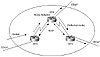
Figure 8-2 Internal peers
using a route reflector.
In an AS where routers have to build BGP sessions with too many
other routers, the route reflector concept becomes very helpful and
very scalable.
Naming Conventions and Rules of
Operation
The route reflector is a router that can perform the route
reflection function. The IBGP peers of the route reflector fall
under two categories, clients and nonclients. A route
reflector and its clients form a cluster. All peers of the route
reflector that are not part of the cluster are non-clients. Figure
8-3 illustrates these components.
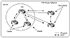
Figure 8-3 Route
reflection process components.
Non-clients must be fully meshed with the route reflector and
each other because they follow the basic rules of the IBGP mesh.
Clients should not peer with internal speakers outside their
associated cluster. As you can see, these conditions have been met
for the clients and non-clients in figure 8-3.
The route reflector function is implemented only on the route
reflector; all clients and non-clients are normal BGP peers that
have no notion of the route reflector. Clients are only considered
as such because the route reflector lists them as clients.
Any route reflector that receives multiple routes for the same
destination will pick the best path based on the usual BGP decision
process.The best path would be propagated inside the AS based on the
following rules of operation (propagation to EBGP runs as
usual):
- • If the route is received from a non-client
peer, reflect to clients only.
- • If the route is received from a client
peer, reflect to all non-client peers and also to client peers,
except the originator of the route.
- • If the route is received from an EBGP
peer, reflect to all client and non-client peers.
|
Redundancy Issues and Multiple Route Reflectors in an
AS
With the lack of a full BGP mesh inside the AS, redundancy and
reliability become issues. If a route reflector fails, clients will be
isolated. Redundancy requires the existence of multiple route reflectors
in an AS where clients can simultaneously peer with multiple routers. If
one peer connection fails, the other will back it up.
The importance of complementing logical redundancy with physical
redundancy cannot be overstated. It does not make sense to build route
reflector redundancy if the physical redundancy itself does not exist.The
logical redundancy arrangement on the left in figure 8-4 shows RTA as the
client of both RR1 and RR2. RTA is peering with both route reflectors in
an effort to create a redundant link. Unfortunately, if the connection to
RR1 is broken, or if RR1 itself fails, RTA is isolated. The logical
connectivity between RTA and RR2 is of no practical use and is simply more
memory and processing overhead.
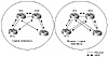
Figure 8-4 Comparison of
logical and physical redundancy solutions.
The physical redundancy configuration on the right in figure 8-4
illustrates how logical redundancy can be backed up with physical
redundancy. In the event of a failure in the link to RR1, RTA can reach
RR2.
The Big Picture
National networks are usually laid out in concentration points per
geographical regions. Providers have POPs (sometimes called hubs)
in different regions in the U.S. with high-speed DS3 or OC3/OC12 links
connecting different locations in a partially meshed topology. The route
reflector concept can be used to logically interconnect the routers
running BGP in a pattern that follows the physical connectivity. Figure
8-5 illustrates a complex arrangement featuring route reflectors
(indicated as RR in this figure and those that follow).
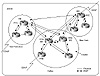
Figure 8-5 Complex multiple
route reflector environment.
Except for the fact that the route reflector needs to keep up with more
BGP sessions than normal routers, any router could be configured as a
route reflector. Your physical topology should be the main indicator of
which is the best router to choose to be the route reflector.
In figure 8-5, AS100 is divided into three clusters: San Francisco,
Dallas, and New York. The Dallas cluster has multiple RRs for redundancy.
RTA and RTD physically connect San Francisco to New York. It makes sense
to follow the actual physical traffic flow in selecting RRs, so RTA and
RTD are the obvious choices for RRs in the Dallas cluster.
In San Francisco, router RTC physically connects San Francisco to
Dallas, so RTC would be the best candidate to become a RR. The same
reasoning applies for the New York cluster: RTE physically connects New
York to Dallas and is the best candidate for RR.
The Route Reflector Preserves IBGP
Attributes
The route reflector concept does not change the IBGP behavior. The
route reflector is not allowed to change the attributes of the reflected
IBGP routes. The next hop attribute, for example, remains the same when
exchanged between RRs. This is necessary for avoiding loops in the AS.
Figure 8-6 illustrates why the RR should not modify the attributes of
the IBGP reflected routes. The next hop attribute is used as an example.
Figure 8-6 focuses on the portion of the network from figure 8-5 where
Dallas connects to San Francisco.
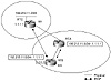
Figure 8-6 The route reflector
preserves IBGP attributes.
Assume that RTB is specified as the route reflector, rather than RTA,
and that an IBGP session is configured between RTB (2.2.2.2) and RTC
(1.1.1.1). This looks odd because physically RTA is passing the traffic,
while logically RTB is reflecting the BGP updates between RTA and RTC. RTB
will receive the prefix 192.213.11.0/24 from its IBGP neighbor RTC with a
next hop of 1.1.1.1. RTB will reflect the route to its client RTA with the
next hop 1.1.1.1 also. This is the desired behavior.
Alternatively, if RTB were to change the next hop to its IP address,
2.2.2.2, RTA would try to use RTB to reach destination 192.213.11.0/24. A
loop would occur between RTA and RTB, with RTA sending the traffic to RTB,
and RTB trying to use RTA to reach the final destination. This
hypothetical situation exemplifies why the route reflector must not change
IBGP behavior and attributes.
Avoiding Loops
When dealing with the possibility of routing updates making their way
back into an AS, BGP relies on the information in the AS_path for loop
detection. An update that tries to make its way back into the AS it was
originated from will be dropped by the border router.
With the introduction of route reflectors, there is a potential for
having routing loops within an AS. A routing update that leaves a cluster
might find its way back inside the cluster. Loops inside the AS cannot be
detected by the traditional AS_path approach because the routing updates
have not left the AS yet. BGP offers two extra measures for loop avoidance
inside an AS when route reflectors are configured.
Using an Originator ID
The originator ID is a 4-byte, optional, nontransitive BGP
attribute (type code 9) that is created by the route reflector. This
attribute carries the router ID of the originator of the route in the
local AS. If, because of poor configuration, the update comes back to the
originator, the originator ignores it.
Troubleshooting:
Using originator IDs and cluster
lists to avoid loops in ASs using route reflectors.
Using a Cluster List
The cluster list is an optional, nontransitive BGP attribute
(type code 10). Each cluster is represented with a cluster ID.
A cluster list is a sequence of cluster IDs that an update has
traversed. When a route reflector sends a route from its clients to
nonclients outside the cluster, it appends the local cluster ID to the
cluster list. If the route reflector receives an update whose cluster list
contains the local cluster ID, the update is ignored. This is basically
the same concept as the AS_path list applied between the clusters inside
the AS.
Route Reflectors and Peer Groups
Recall from Chapter 5, "Tuning BGP Capabilities," that a peer group is
a group of BGP neighbors that shares the same routing policies. Route
reflectors can be used in conjunction with peer groups only when the
clients of a route reflector are fully meshed. The reasoning is as
follows: in a normal situation, a router A that learns a prefix from a
router B will send a WITHDRAWN message back to that router to poison that
route. In other words, router A is telling B that this prefix is not
reachable via A. This is to prevent a situation where A claims that a
prefix is reachable via B, and B claims it is reachable via A. In a peer
group, the same UPDATE or WITHDRAWN message is sent to all members of the
group. In a peer group/route reflector situation, a route reflector that
has learned a prefix from one of the clients and is trying to poison that
route will end up withdrawing that prefix from all the other clients.
Because the clients are not talking to one another via BGP, that prefix
will be lost. That is why an IBGP mesh between the clients is needed for
the other clients to learn that prefix directly from the source. Even with
this design, the network administrator is still avoiding a full IBGP mesh
between all IBGP routers in the AS and concentrating the mesh between
route reflectors and clients.
With the use of peer groups, the AS design would look like rings of
fully meshed BGP speakers. Route reflectors are fully meshed among each
other, and clients of each route reflector are also fully meshed. Figure
8-7 illustrates such an environment; each circled area represents a
distinct peer group.
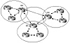
Figure 8-7 Route reflectors and
peer groups.
In conclusion, the route reflector concept is growing in popularity for
large networks due to the fact that it is a simple approach that enables
scalability without too much overhead. Migrating from a non-route
reflector to a route reflector design is easy because only the route
reflectors need to be modified to behave as route reflectors; all other
routers would be running as usual. Routers that do not implement the route
reflector behavior could be part of the AS without any loss of BGP routing
information.
Confederations
Confederation [2] is another way to deal with the explosion of
an IBGP mesh within an AS. As with route reflection, confederation is
recommended only for cases in which the IBGP peering exceeds about 100
peering sessions per router.
Troubleshooting:
Ch. 11, pp. 426-432.
Confederations
Confederation is based on the concept that an AS can be broken into
multiple sub-ASs. Inside each sub-AS, all the rules of IBGP apply. All BGP
routers inside the sub-AS, for example, must be fully meshed. Because the
sub-ASs each have a different AS number, external BGP must run between
them. Even though EBGP is used between sub-ASs, routing inside the
confederation behaves like IBGP routing in a single AS. In other words,
the next hop, MED, and local preference information is preserved when
crossing the sub-AS boundaries. To the outside world, a confederation
looks like a single AS. Figure 8-8 illustrates an example of a
confederation.
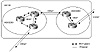
Figure 8-8 Example
confederation of sub-AS constructs.
In figure 8-8, AS100 is split into two sub-ASs: AS65050 and AS65060.
The AS as a whole is now one large confederation, identified by a single
confederation number, 100. All the sub-ASs are shielded from the outside
world and can be given any AS numbers. The numbers could be chosen from
the private AS list in order not to use up any formal AS numbers.
IBGP full mesh is used within the sub-ASs, and EBGP is used between the
sub-ASs, as well as between the confederation itself and outside ASs.
Confederations can easily detect routing loops inside the AS because EBGP
is run between sub-ASs. The AS_path list is used to detect routing updates
that leave a sub-AS and try to reenter the same sub-AS. A routing update
that tries to reenter a sub-AS it originated from will be detected because
the sub-AS will see its own sub-AS number listed in the AS_path of the
update.
The drawback with confederations is that migration from a
nonconfederation to a confederation design requires major reconfiguration
of the routers and a major change in the logical topology. In addition,
routing through a confederation might not take an optimal path without
manually setting BGP policies. Figure 8-9 illustrates this issue.
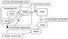
Figure 8-9 AS confederation
internal and external routing.
Confederation 100 is composed of three sub-ASs: 65010, 65020, and
65030. The AS_path within confederation 100 is represented by the sequence
of ASs the route has traversed all considered to be the same length, which
would introduce routing suboptimality inside the AS. From the point of
view of sub-AS 65030, AS_path (65010) is the same length as AS_path (65020
65010); traffic inside the confederation may take either path. Additional
policies would have to be set to affect routing behavior. Local
preference, for example, can be configured to make AS_path (65010)
preferred over (65020 65010).
For external ASs, the confederation is a single AS, and the route taken
inside the confederation is not known. This is misleading for ASs that
base their routing policies on the AS_path length. To reach AS200, AS300
will most likely prefer to go via confederation 100 because the path looks
shorter than the path via AS400 and AS500. In actuality, of course,
confederation 100 is not the shortest path because it includes a path via
three ASs, whereas the alternative (AS400 AS500) only includes two. AS300
will never know of this pitfall unless the AS100 confederation design is
disclosed.
Even though routes are exchanged between sub-ASs via EBGP, all the IBGP
rules still apply to have the whole AS behave as a single entity. The EBGP
next hop is still carried within the AS as well as the metric and local
preference values.
As far as the BGP decision algorithm, the only changes are in the way
BGP routes to outside the confederation compared to how BGP routes inside
the confederation. Without confederations, EBGP routes are preferred over
IBGP routes. With confederations, we have introduced new types of EBGP
route between the sub-ASs, called a confederation external route.
BGP prefers routes in the following manner: EBGP routes to outside the
confederation > confederation exterior routes > IBGP routes. This
means if BGP has a choice between two paths to the same destination, one
outside the confederation and one inside, BGP will pick the exterior path.
If BGP has a choice between two paths to the same destination—one inside
the sub-AS and one outside the sub-AS—BGP will pick the one exterior to
the sub-AS. This is, of course, assuming that all other attributes are the
same.
Recommended Confederation Design
Choosing and connecting the sub-ASs randomly inside the confederation
will lead to problems. Unnecessary processing will occur because each
sub-AS will end up getting similar information from other sub-ASs.
Besides, suboptimality will be introduced due to the fact that all paths
inside the AS have exactly the same length, as already discussed.
Experience shows that a centralized confederation design leads to the
best behavior. Centralized design means that all sub-ASs will exchange
information with each other via a central sub-AS backbone.
With the example illustrated in Figure 8-10, each sub-AS will have
interaction with only one other sub-AS, and routing will be more uniform
as far as path length and route exchange within the confederation.
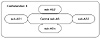
Figure 8-10 Centralizing
confederation.
Confederations or Route Reflectors
Determining whether you should use route reflectors or confederations
is not a simple decision. Different organizations have experienced
different levels of stability with either approach. Cisco recommends the
use of the route reflector technique to solve the IBGP mesh issues. Route
reflectors have proven to be more flexible to deploy. On the other hand,
confederations could be used to run an IGP in one sub-AS independently of
IGPs in other sub-ASs, which would help in controlling the instabilities
of large IGPs.
In some situations, both approaches, route reflectors and
confederations, can be used in conjunction with each other. An AS can be
divided into sub-ASs that are running route reflectors.
Whichever approach you use, you should always understand the
restrictions and behavior of each method and design your network
accordingly.
Controlling IGP
Expansion
One of the ways in which administrators push their networks to the
limit is by letting them grow in size in such a way that the IGP will be
hard to manage. Whether the IGP is as outdated as RIP version 1 or as
advanced as OSPF and ISIS, the issue of scalability will arise. So far,
this chapter has discussed route reflectors and confederations as ways of
managing IBGP growth. A scalable way of managing IGP expansion is to
segment the AS into multiple regions, each running a single, distinct IGP.
The individual regions, in turn, must be connected via BGP. With this
design, the stability of one region would not affect the stability of
another.
What criteria should network designers and architects follow in
deciding whether their networks need segmentation? One thing is for sure:
the Internet is one huge network that cannot be handled by running an IGP,
and that is why it is segmented by BGP.
So what constitutes a large or small network? Is it the number of
routers or the number of routes, and if so, what number? You will hear
different answers based on different administrators' experiences. The
general answer to this question depends mainly on how robust the IGP, what
tools it can offer to control the route explosion and instability, and
whether BGP segmentation represents a more beneficial, less costly (in
dollars and effort) method than relying on the IGP's tools.
Protocols such as OSPF and ISIS offer certain hierarchical methods that
can control route instabilities and provide means for route summarization.
But even with these methods, the IGP can grow beyond control. A working
guideline for today's networks is that IP routing tables having 2,000 to
3,000 IGP interior routes may have reached a limit and need a closer look
to make sure that they do not grow further. It is not the number of routes
that cause problems, because BGP transit routers today are carrying more
than 42,000 Internet routes with no problem. What causes problems is
situations, such as hardware and access line instabilities, where these
routes end up bouncing and trying to converge, causing what is known as a
network "meltdown."
Does this mean that networks with 3,000 IGP routes need to be segmented
via BGP? The answer is, not necessarily. In most cases, a redesign of the
IGP itself with more emphasis on using the IGP segmentation and
summarization techniques can bring down the number of routes to a
manageable level.
To understand why the decision to control growth with BGP segmentation
should be approached with caution, you need to understand what is
compromised when ASs are segmented. The main strength of IGPs, especially
IGPs based on Link State protocols, has always been convergence; that is,
their capability to quickly adapt to network changes. Another strength is
their capability to develop a level of redundancy and load balancing.
BGP, on the other hand, was created to implement policies across AS
boundaries, with no major emphasis on convergence. When segmenting with
BGP, convergence will be enhanced within the newly created smaller
segments, but might diminish when crossing sub-AS boundaries because of
the dependency of BGP on TCP sessions to carry routing updates.
Another drawback is the additional user intervention needed to control
and manage the BGP policies that are automatically imposed on the routing
behavior. As you have seen in this book, attribute manipulation is so far
the only tool to manipulate routing behaviors. With the introduction of
more ASs, what used to be simple IGP routing is no longer the case.
Understanding all these issues will help designers develop a realistic
approach to designing their networks.
This section discusses two methods of segmenting the AS:
- • Multiple regions separated by IBGP
- • Multiple regions separated by EBGP
Using Confederation to Control IGP
Expansion
Confederations can also be used to control the expansion of IGPs.You
have already seen how a confederation can divide the AS into multiple
smaller sub-ASs. If each sub-AS is running a different IGP, then the
centralized design described in would be a viable approach. The IGPs are
now running independently of one another, and the whole AS is still
considered as a single entity to the outside world. Each IGP will be
injected into BGP for interregional connectivity. Internal non-BGP routers
in each region will default to the BGP border router, which contains all
routes. Internet connectivity can be provided via the central AS to
provide a central default for all the different regions. This is similar
to the scenario in figure 8-15.
On the negative side, confederations require extra configuration and do
not provide the capability of setting policies between the sub-ASs because
the whole AS is still considered one entity. Besides, any confederation
design that is not centralized could introduce further complications in
route optimality inside the confederation.
Virtual Private Networks with
Route Reflectors
Virtual Private Networks (VPNs) are private networks in the
sense that they require traffic exchange within their network boundaries
and no access to or from other networks that are not part of the VPN.
Providers and large enterprises are faced every day with the challenges of
private data exchange. A large organization with different geographic
locations, for example, serviced by a large provider, may want to restrict
which regions can exchange traffic with each other. It is then the
provider's duty to provide this level of privacy. Similarly, an enterprise
that is a collection of smaller business units might want to implement
data exchange restrictions between the units. So far, the only way to
achieve this behavior is via packet filters and traffic pipes (tunnels),
which protect information from being exchanged between private entities.
This section attempts to find a solution to this problem using a route
reflector hierarchical concept.
We will conceptualize a large AS, as shown in figure 8-16, as
consisting of three hierarchical levels: customers (Level 3), distribution
(Level 2), and core (Level 1). Customer, in this sense, means a unit or
region that has the same data access and restriction criteria. Each
distinct group of customers is served by a distinct Virtual Private
Network. Figure 8-16 contains two such VPNs, VPN1 and VPN2.
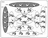
Figure 8-16 Route reflector
hierarchy.
Level 3 (L3), the customer level, is following a 0/0 default toward
Level 2 (L2), the distribution level. At the customer level, the only
routes exchanged are the ones generated locally. To reach other parts of
the VPN, the customer will send its traffic toward the distribution level.
The customer router is announcing its routes toward the distribution
routers (L2) with a specific BGP community that is representative of its
particular VPN. In figure 8-16, VPN1 is announcing its routes with a
community C1, whereas VPN2 is announcing its routes with a community C2.
At Level 2, the distribution routers will receive the routing updates
and will propagate (reflect) them to Level 1, the core routers. As such,
the core routers will have all the VPN routes tagged with the VPN
community. The core routers in turn will advertise these routes only to
the distribution that can service a particular VPN. That means a
distribution router that is servicing VPN1 will receive only routes that
belong to VPN1. The distribution routers of VPN1 will not carry any routes
of the other VPNs.
To understand the outcome of this design, consider two cases. In the
first case, a customer in VPN1 is trying to access another customer in
VPN1. In the second case, a customer in VPN1 is trying to access a
customer not in VPN1.
In the first case, if the destination is within Level 3, the customer
router would have the specific route in its routing table. If the
destination is not in Level 3, the customer has no choice but to follow a
0/0 default toward Level 2. At Level 2, because the distribution router
has knowledge of all VPN1 routes via the core, the distribution router
will forward the traffic toward the core router. At the core, all
destinations are known, and the traffic will be delivered to its
destination in VPN1.
In the second case, the customer of VPN1 is trying to access a
destination not inside VPN1. The traffic will follow the 0/0 default
toward Level 2. At the distribution level, the routers have no knowledge
of any destinations other than VPN1, and the traffic will be dropped. This
will preserve the private aspects of the VPNs.
It is important to note, in this scenario, that the service provider is
not providing global connectivity (Internet connectivity), but rather
connectivity just among the different components of the organization
(intranet connectivity). In fact, in this route reflector approach to
servicing VPNs, Internet connectivity for the VPNs cannot be achieved.
This is because Level 3 has to follow defaults toward the distribution and
cannot follow a default toward the Internet. In addition, if Internet
connectivity were provided on the distribution level, then customer
traffic toward a different VPN could be rerouted to that VPN via the
Internet, which defeats the purpose of VPNs. Finally, if Internet
connectivity were provided via the core, then customer traffic would not
be able to reach the Internet because the traffic will be dropped at the
distribution router, which would not have the route in its routing
table.
Given that private networks are supposed to be private, Internet
connectivity might not be a requirement. For an organization that wants
both VPNs and Internet connectivity, a method other than this specific
hierarchical route reflector approach must be used.
Looking Ahead
You have seen so far how BGP can be a powerful tool in giving routing a
more structured look. You have learned how to manipulate traffic and how
to segment the AS into more controlled elements. One more aspect that
needs discussion is route instabilities on the Internet. Many factors
induce route fluctuations and, in turn, traffic fluctuations. Some of
these elements can be avoided and some are beyond your control. The
Internet has become a necessity for everyday operations; it is in your
best interest to respect and protect its integrity. The following chapter
discusses the causes of route instability and some of the measures taken
to stop or at least dampen its effect.
Frequently Asked
Questions
Q—I have a SF hub and a SJ hub. Do you think it is
better to separate them into different ASs and run BGP instead of
running an IGP in between?
A—This doesn't sound like a candidate for segmentation via
BGP. Remember that even though segmentation gives better hierarchy
and control, it introduces more routing policies dictated by the BGP
behavior. In small networks such as yours, you could achieve the
same stability by running an IGP.
Q—I do not have enough BGP peers to justify using route
reflectors. What happens if I use them anyway?
A—You will achieve normal routing. You just need to
understand that with this model, you rely on centralized routers for
running BGP sessions. The RR has to do more processing, and it
becomes a single point of failure. Hence, you have to do more
provisioning for redundancy. You also will have to deal with other
issues such as peer groups and attribute modification, as described
in this chapter. If you think that the overhead is not an issue,
configuring RRs is no problem.
Q—With confederations, an EBGP external route is more
preferred than a confederation external route. Does that mean that I
can never use another sub-AS as an exit point?
A—No. You could always use attributes such as local
preference to prefer whichever exit point you want.
Q—Because local preference is not passed between ASs,
it won't be passed between sub-ASs inside a confederation,
correct?
A—That is not true. Using additional configuration, the
sub-AS will know that it is talking to an external peer inside a
confederation and will maintain all attributes that are normally
maintained by IBGP.
Q—I need to configure route reflectors, but the current
software on my routers does not support it. Do I need to upgrade all
my routers at the same time?
A—No. You only need to upgrade the routers that will
become RRs. Other routers will behave as any conventional IBGP
speaker. This will help you migrate your network to the new design
in a structured way. |
References
[1] RFC 1966 BGP Route Reflection an Alternative to Full Mesh IBGP
[2] RFC 1965 Autonomous System Confederations for BGP
Previous
| Content |
Next


