Chapter 5. Tuning BGP Capabilities
This chapter covers the following key topics:
- • Building Peer Sessions
A walk-through of the negotiation process between BGP and its neighbors.- • Sources of Routing Updates
The source and method by which routes get injected into BGP has implications for the accuracy and stability of routing information.- • Overlapping Protocols: Backdoors
When alternate routes into and out of a network are offered by overlapping protocols, a method of ranking them by preference is available.- • The Routing Process Simplified
The decision model by which BGP receives, filters, selects for usage, and advertises routes, as a continuous process.- • Controlling BGP Routes
At the core of BGP is a collection of attributes that administrators can apply to control routing according to their networks' needs.- • Route Filtering and Attribute Manipulation
An example-oriented, step-by-step look at how BGP permits or denies routes, applies filters, and manipulates attributes to define the set of routing updates that enter and exit an AS.- • BGP4 Aggregation
Several specific scenarios involving different aggregation choices and how BGP4 accommodates them. - • Sources of Routing Updates
Up to this point, this book has been concerned primarily with general definitions of interior and exterior gateway protocols and an overview of their respective and interconnected tasks. The Border Gateway Protocol was also presented from the technical perspective of its functional elements. With this chapter, you will begin to consider more practical implementation details for BGP as part of the overall design problem in building reliable Internet connectivity. This chapter examines specific attributes of BGP and how they are applied individually and together to address this design problem. Although the terminology, attributes, and details of this chapter are specific to BGP, the general concepts and problems raised are pertinent to routing architecture design, regardless of what specific protocols are being utilized.
Building Peer Sessions
The previous chapter began examining the process of BGP neighbor negotiation at a fairly technical level and with an emphasis on the formats of messages exchanged during negotiation. This chapter now expands the examination to consider additional subtleties of the negotiation process. In addition, distinctions between internal and external BGP, which have practical implications in building peer sessions, are introduced in this section.
Although BGP is meant to be used between autonomous systems to provide an interdomain loop-free topology, BGP can be used within an AS as a pipe between border routers running external BGP to other ASs. A neighbor connection, also called a peer connection, between two routers can be established within the same AS, in which case BGP is called internal BGP (IBGP). A peer connection can also be established between two routers in different ASs. BGP is then called external BGP (EBGP). Figure 5-1 contrasts these environments.

Figure 5-1 Internal and
external BGP implementations.
Upon neighbor session establishment and during the OPEN message exchange negotiation, peer routers compare AS numbers and determine whether they are peers in the same AS or in different ASs. The difference between EBGP and IBGP manifests itself in how each peer would process the routing updates coming from the other peer and in the way different BGP attributes are carried on external versus internal links.
The neighbor negotiation process is mainly the same for internal and external neighbors as far as building the TCP connection at the transport level. It is essential to have IP connectivity between the two neighbors for the transport session to take place. IP connectivity has to be achieved via a protocol different from BGP; otherwise, the session will be in a race condition. An example of a race condition follows: neighbors can reach one another via some IGP, the BGP session gets established, and the BGP updates get exchanged. The IGP connection goes away for some reason, but still the BGP TCP session is up because neighbors can still reach each other via BGP. Eventually the session will go down because the BGP session cannot depend on BGP itself for neighbor reachability.
Troubleshooting:
Verifying neighbor reachability for the TCP session to come up.
An Interior Gateway Protocol (IGP) or static route can be configured to achieve IP connectivity. In essence, a ping packet, containing a source IP address (the IP address of one BGP peer) and a destination IP address (the IP address of the second peer), must succeed for a transport session to initiate.
Physical Versus Logical Connections
External BGP neighbors have a restriction on being physically connected. BGP drops any updates from its external BGP peer if the peer is nonconnected. Some situations, however, arise where external neighbors cannot be on the same physical segment. Such neighbors are logically, but not physically connected. An example would be running BGP between external neighbors across non-BGP routers. In this situation, Cisco offers an extra knob to override this restriction. BGP would require some extra configuration to indicate that its external peer is not physically attached.
Troubleshooting:
Nondirectly connected external neighbors need extra configuration.
In Cisco's implementation, nondirectly connected EBGP peers are referred to as EBGP multihop. In figure 5-2, RT2 is not able to run BGP, but RT1 and RT3 are. Thus, external neighbors RT1 and RT3 are logically connected and peer with one another via EBGP multihop.

Figure 5-2 External BGP
multihop environment.
On the other hand, neighbors within the same autonomous system (internal neighbors) have no restrictions whatsoever on whether the peer router is physically connected. As long as there is IP connectivity between the two neighbors, BGP requires no extra configuration. In figure 5-2, RT1 and RT4 are logically but not physically connected. Because both are in the same AS, no additional configuration is needed for them to run IBGP.
Obtaining an IP Address
The neighbor's IP address could be the address of any of the routers' interfaces, such as Ethernet, Token Ring, or Serial. Keep in mind that the stability of the neighbor connection will rely on the stability of the IP address you choose.
Troubleshooting:
Session stability depends on stability of neighbor IP addresses.
If the IP address belongs to an Ethernet card that has some hardware problems and is shutting down every few minutes, the neighbor connection and the stability of the routing updates will suffer. Cisco has introduced a loopback interface; this is actually a virtual interface that is supposed to be up at all times. Tying the neighbor connection to a loopback interface will make sure that the session is not dependent on any hardware interface that might be problematic.
Adding loopback interfaces is not necessary in every situation (it actually requires more configuration). If external BGP neighbors are directly connected and the IP addresses of the directly connected segment are used for the neighbor negotiation, a loopback address is of no added value. If the physical link between the two peers is problematic, then the session will break with or without loopback.
Troubleshooting:
Ch. 10, pp. 300-305. Building Peering Sessions
Authenticating the BGP Session
As you have already seen in Chapter 4, "Interdomain Routing Basics," the BGP message header allows authentication. Authentication is a measure of precaution against hackers who might present themselves as one of your BGP peers and feed you wrong routing information. Authentication between two BGP peers gives the capability to validate the session between you and your neighbor by using a combination of passwords and keys upon which you both agree. A neighbor that tries to establish a session without the use of these specific passwords and keys will not be permitted. The authentication feature uses the Message-Digest Algorithm version 5 (MD5) [1]. The discussion of the authentication algorithm itself is beyond the scope of this book.
BGP Continuity Inside an AS
To avoid creating routing loops inside the AS, BGP does not advertise to internal BGP peers routes that are learned via other IBGP peers. Thus, it is important to maintain a full IBGP mesh within the AS—that is, every BGP router in the AS has to build a BGP session with all other BGP routers inside the AS. Figure 5-3 illustrates one of the common mistakes administrators make when setting BGP routing inside the AS.

Figure 5-3 Common BGP
continuity mistake.
Troubleshooting:
Building full IBGP meshes to ensure connectivity.
In the situation illustrated in figure 5-3, an ISP has three POPs (Point Of Presence) in San Jose, San Francisco, and Los Angeles. Each POP has multiple non-BGP routers and a BGP border router running EBGP with other ASs. The administrator sets an IBGP connection between the San Jose border router and the San Francisco border router. He sets another IBGP connection between the SF border router and the LA border router. In this configuration, EBGP routes learned via SJ will be given to SF, EBGP routes learned via SF are given to SJ and LA, and EBGP routes learned via LA are given to SF. Routing in this picture is not complete; EBGP routes learned via SJ will not be given to LA, and EBGP routes learned via LA will not be given to SJ. This is because the SF router will not pass on IBGP routes between SJ and LA. What is needed is an additional IBGP connection between SJ and LA (shown via the dotted line). You will see in Chapter 8, "Controlling Large-Scale Autonomous Systems," how this situation could be handled by using the concept of route reflectors, an option that scales much better in cases where the AS has a large number of IBGP peers.
Synchronization Within an AS
BGP must be synchronized with IGP in such a way that it waits until the IGP has propagated routing information across your autonomous system before advertising transit routes to other ASs. It is important that your AS be consistent about the routes it advertises. If, for example, your BGP were to advertise a route before all routers in your AS had learned about the route through the IGP, your AS could receive traffic that some routers cannot yet route.
Whenever a router receives an update about a destination from an IBGP peer, the router tries to verify internal reachability for that destination before advertising it to other EBGP peers. The router would do so by checking for the existence of this destination in the IGP. This would give an indication whether non-BGP routers can deliver traffic to that destination. Assuming that the IGP recognizes that destination, the router will announce it to other EBGP peers. Otherwise, the router will treat the route as not being synchronized with the IGP and would not advertise it.
Consider the situation illustrated in figure 5-4; ISP1 and ISP2 are using ISP3 as a transit AS. ISP3 has multiple routers in its AS and is running BGP only on the border routers. (Even though RTB and RTD are carrying transit traffic, ISP3 has not configured BGP on these routers.) ISP3 is running some Interior Gateway Protocol inside the AS for internal connectivity.

Figure 5-4 BGP route
synchronization.
Assume that ISP1 is advertising route 192.213.1.0/24 to ISP3. Because RTA and RTC are running IBGP, RTA will propagate the route to RTC. Note that other routers besides RTA and RTC are not running BGP and have no knowledge so far of the existence of route 192.213.1.0/24.
In the situation illustrated in figure 5-4, if RTC advertises the route to ISP2, traffic toward the destination 192.213.1.0/24 will start flowing toward RTC. RTC will do a recursive lookup in its IP routing table and will direct the traffic toward the next hop RTB. RTB, having no visibility to the BGP routes, will drop the traffic because it has no knowledge of the destination. This has happened because there is no synchronization between BGP and the IGP.
The BGP rule states that a BGP router should not advertise to external neighbors destinations learned from inside BGP neighbors unless those destinations are also known via IGP. If a router knows about these destinations via IGP, it assumes that the route has already been propagated inside the AS, and internal reachability is guaranteed.
Troubleshooting:
Synchronizing BGP and IGP to advertise routes.
The consequence of injecting BGP routes inside an AS is costly. Redistributing routes from BGP into the IGP will result in major overhead on the internal routers, which might not be equipped to handle that many routes. Besides, carrying all external routes inside an AS is not really necessary. Routing can easily be accomplished by having internal non-BGP routers default to one of the BGP routers. Of course, this will result in routing suboptimality (there is no guarantee for shortest path for each route), but this cost is minimal compared with maintaining thousands of routes inside the AS.
Cisco offers a software knob called "no synchronization" that enables BGP to override the synchronization requirement and enables it to advertise routes learned via IBGP irrespective of an existence of an IGP route. In practice, a couple of situations exist where synchronization can be safely turned off on border routers:
- • When all transit routers inside the AS are
running fully meshed IBGP. In this situation, internal
reachability is guaranteed because a route that is learned via
EBGP on any of the border routers will automatically be passed on
via BGP to all other transit routers.
- • When the AS is not a transit AS.
Sources of Routing Updates
In networks as complex as today's Internet, route stability is a big issue. There is a close correspondence between route fluctuations and the stability of the Internet access links on one hand and how the routing information was injected into the Internet via BGP on the other hand. Information can be injected into BGP dynamically or statically. Dynamically injected routes come and go from the BGP routing table, depending on the status of the networks they identify. Statically injected routes are constantly maintained by the BGP routing tables, regardless of the status of the networks they identify. Thus, while a dynamic advertisement will cease if the network being advertised no longer exists, a static advertisement would not. Each method has its pros and cons, as you will see next.
Troubleshooting:
Example: Ch. 10, pp. 315-324. Sources of Routing Updates
Unstable Routes
Injecting the IGPs in BGP dynamically or semidynamically results in the dependency of the BGP routes on the IGP routes. Although you could argue that this is good because it reflects the actual status of networks, it can have drawbacks as well. Remember that with today's global network connectivity, route fluctuation within your AS will affect your provider if you are a customer or other providers if you are a provider. The IGP route you advertise will translate into a BGP route. If that route goes down, a WITHDRAWN message will be sent via BGP requesting peers to remove that route from their tables. A route constantly going up and down in your AS has the effect of being constantly sent and withdrawn by other ASs. The example of one fluctuating route is very simplistic; imagine having hundreds of these routes fluctuating in hundreds of ASs. Internet stability will be affected very negatively.
Strict measures are being put in place to try to mitigate the effect of route fluctuation on the Internet. As you will see in Chapter 9, "Designing Stable Internets," by a process called route dampening, fluctuating routes are penalized and stopped from being advertised depending on their degree of instability. Your routes might be "held hostage" for minutes and hours—until they stabilize—by an interconnected provider.
Controlling route instability is not an easy matter because it usually depends on factors that are beyond your control. Such factors could be instable access links or faulty hardware. One way to minimize route instability is aggregation. When the aggregate represents more than one route, the fluctuation of any single route does not cause fluctuation in the aggregate itself. Aggregation could be done on the customer boundary or the provider boundary, depending on the level of information exchanged between the customer and the provider. If done on the customer boundary, this would alleviate the provider from seeing the fluctuations of individual customer routes. If aggregation is done on the provider boundary, then the customer fluctuation would leak to the provider but will not be propagated to the Internet. BGP4 aggregation is discussed at the end of this chapter after you have acquired enough techniques in BGP tuning.
Another way of controlling route instability is to decouple route advertisement from the existence of the route itself. This is called static injection of routes into BGP, as described in the following section.
Injecting Information Statically into BGP
Today, injecting information statically into BGP has proven to be the most effective in ensuring route stability. Of course, this method also has drawbacks.
To statically inject information into BGP, IGP routes (or aggregates) that need to be advertised to other peers are manually defined as static routes. This ensures that these routes will never disappear from the IP routing table and hence will always be advertised. Because administrators are often uncomfortable advertising routes to networks that might be down or unreachable, the appropriateness of injecting information statically depends on the particular situation.
Troubleshooting:
Example: Ch. 10, pp. 323-324. Injecting Information Statically into BGP
If, for example, the route is advertised to the Internet from a single point, then advertising a route that is actually down is not a big issue. Hosts trying to access that destination will fail irrespective of whether the route is advertised.
On the other hand, if a route is advertised to the Internet from multiple points, then advertising the route statically at all times might end up black-holing the traffic. If problems inside the AS prevent the border router from being able to reach the network it is advertising, traffic to that destination will be dropped even though it could have been reached from some other entry point.
The actual advertisement of the static route can be done with either of the methods described in the "Injecting Information Dynamically into BGP" section. Advertisement can be done by redistributing all the static routes via the redistribute command or a subset of the static routes via the network command. The latter method enables a more controlled route injection because redistribution might cause some unwanted static routes to be sent via BGP.
ORIGIN of Routes
BGP considers the networks advertised via the network command or via aggregation as being internal to the AS and will include the ORIGIN attribute in each route as being IGP (i). On the other hand, whenever a route is injected into BGP via redistribution (whether statically or dynamically), the ORIGIN of the route will be INCOMPLETE because the redistributed routes could have come from anywhere.
Figure 5-6 illustrates these issues. In Scenario 1, all networks have been listed under the BGP process via the network command. Note that BGP has considered 10.0.0.0 and 11.0.0.0 as having a known origin of IGP. Network 12.0.0.0 is the only network that is not known to the router (does not exist in the IP routing table). As you can see, 12.0.0.0 is not being advertised via BGP, even though it has been listed via the network command.

Figure 5-6 Behavior
comparison for the ORIGIN attribute.
In Scenario 2, networks 10.0.0.0, 11.0.0.0, and 12.0.0.0 have been statically defined. Network 11.0.0.0 has also been defined via the network command. Finally, network 13.0.0.0 is learned dynamically by the router via IGP. All these networks have been injected into BGP via redistribution. As a result, networks 10.0.0.0, 12.0.0.0, and 13.0.0.0 have been advertised with an ORIGIN of INCOMPLETE because these networks have been injected into BGP via redistribution.
Although network 11.0.0.0 has been injected via redistribution, it is also defined natively to BGP via the network command, which is why it will be sent out with an ORIGIN of IGP. If it had not been defined natively, it would have been sent out with an ORIGIN of INCOMPLETE. Actually, network 11.0.0.0 did not need to be redistributed because defining it statically and listing it via the network command would suffice to inject it into BGP.
Although the ORIGIN is immaterial at this point, it is used later on to favor one route over the other by the BGP decision process.
An Example of Static Versus Dynamic Routing: Mobile Networks
It is common in the military for units to be mobile; this creates a problem for assigning IP addresses. Usually these mobile units would like to deploy their subnets and IP addresses wherever they go and operate as if they had never moved. If these networks are part of a global network and advertised via BGP, announcing them statically will not work easily. The static commands would have to be removed from the border router of one AS in one location and installed in the border router of another AS in the new location every time the unit moves.
To avoid such complications, injecting these networks dynamically into BGP becomes mandatory. One solution is to inject the IGP into BGP in all locations. This way, whenever the IP addresses are moved from one location to the other, the announcements will disappear from one location and reappear in the new one. In some cases, network administrators are not comfortable with this solution for reasons discussed earlier, such as mutual redistribution problems and the mandate for extensive filtering.
Another possibility is to define these networks in all the border routers of all the locations via the network command. Because BGP checks for the existence of these routes in the IP routing table before announcing them, BGP will only announce the routes in the location of the mobile unit. All other locations will automatically cease from announcing the routes because they are not part of the IGP of that particular AS.
Overlapping Protocols: Backdoors
With different IGPs and EGPs working together to achieve routing, networks can be learned via different protocols. Choosing one protocol over the other affects how the traffic flows. If, for example, traffic follows a RIP route, it might end up on one link; whereas if it follows an external BGP route, it might end up on another link. Backdoor links offer an alternate IGP path that can be used instead of the external BGP path. IGP routes reachable over the backdoor link are called backdoor routes. With the existence of such alternate routes, a mechanism that gives one protocol preference over other protocols is needed. Cisco Systems offers a preference parameter called the distance of a protocol. The lower a protocol's distance, the higher the preference for the protocol. Table 5-1 lists distances according to the Cisco implementation.
|
| |
|---|---|
| Protocol | Distance |
|
| |
| Directly Connected | 0 |
| Static | 1 |
| EBGP | 20 |
| EIGRP (Internal) | 90 |
| IGRP | 100 |
| OSPF | 110 |
| ISIS | 115 |
| RIP | 120 |
| EGP | 140 |
| EIGRP (External) | 170 |
| IBGP | 200 |
| BGP Local | 200 |
| Unknown | 255 |
|
| |
Troubleshooting:
Example: Ch. 10, pp. 324-326. Overlapping Protocols: (Backdoors)
Table 5-1 indicates that a directly connected route is generally preferred over a static route, which in turn is preferred over an EBGP route, and so on. Note that EBGP routes with a distance of 20 are preferred over all the other IGP routes.
Figure 5-7 illustrates the use of backdoor routes. In the figure, AS1 is receiving updates about NetA from two different sources. AS1 is receiving routes via EBGP on the link to AS3 and via the backdoor link running RIP between AS1 and AS2. According to the distance table, the router will give a distance of 20 to the EBGP route and a distance of 120 to the RIP route. In AS1, the EBGP route with the lower distance will be installed in the routing table. Hence, traffic toward NetA will follow the BGP route via AS3 and then AS2, rather than the direct RIP route via AS2.

Figure 5-7 Backdoor
routing conflicts.
Cisco provides a way to force IGP routes to take precedence over the EBGP routes. The concept is simple. EBGP routes can be tagged as backdoor routes. This would set the distance of these routes to be the same as the "BGP Local" route's distance (default is 200). According to table 5-1, this distance is higher than any IGP learned route, and the backdoor IGP route will be preferred.
The Routing Process Simplified
Up until now, this chapter has examined discrete aspects of routing, specifically peer negotiation and static versus dynamic routing. Before diving into details of routing configuration, it makes sense to pause here and briefly overview the BGP routing process in its entirety.
BGP is a fairly simple protocol, which is why it is so flexible. Routes are exchanged between BGP peers via UPDATE messages. BGP routers receive the UPDATE messages, run some policies or filters over the updates, and then pass on the routes to other BGP peers. Cisco's implementation of BGP keeps track of all BGP updates in a BGP routing table separate from the IP routing table. In case multiple routes to the same destination exist, BGP does not flood its peers with all those routes; rather, it picks the best route and sends it. In addition to passing along routes from peers, a BGP router may originate routing updates to advertise networks that belong to its own autonomous system. Valid local routes originated in the system, and the best routes learned from BGP peers are then installed in the IP routing table. The IP routing table is used for the final routing decision.
To model the BGP process, imagine each BGP speaker having different pools of routes and different policy engines applied to the routes. The model would involve the following components:
- • A pool of routes that the router receives
from its peers
- • An Input Policy Engine that can filter the routes or manipulate their attributes
- • A decision process that decides which routes the router itself will use
- • A pool of routes that the router itself uses
- • An Output Policy Engine that can filter the routes or manipulate their attributes
- • A pool of routes that the router advertises to other peers
- • An Input Policy Engine that can filter the routes or manipulate their attributes
Figure 5-8 illustrates this model. The subsequent discussion provides more details about each component.

Figure 5-8 Routing
process overview.
Routes Received from Peers
BGP receives routes from external or internal peers. Depending on what is configured in the Input Policy Engines, some or all of these routes will make it into the router's BGP table.
Input Policy Engine
This engine handles route filtering and attribute manipulation. Filtering is done based on different parameters such as IP prefixes, AS_path information, and attribute information. BGP also uses the Input Policy Engine to manipulate the path attributes to influence its own decision process and hence affect what routes it will actually use to reach a certain destination. If, for example, BGP chooses to filter a certain network number coming from a peer, it is an indication that BGP does not want to reach that network via that peer. Or, if BGP gives a certain route a better local preference (this attribute is discussed later on), it is an indication that BGP would like to prefer this route over other routes.
The Decision Process
BGP goes through a decision process to decide which routes it wants to use to reach a certain destination. The decision process is based on the routes that made it into the router after the Input Policy Engine was applied. The decision process is performed on the routes in the BGP routing table. The decision process looks at all the available routes for the same destination, compares the different attributes associated with each route, and chooses one best route. The decision process is discussed later in this chapter, after coverage of attributes.
Routes Used by the Router
The best routes, as identified by the decision process, are what the router itself uses and are candidates to be advertised to other peers and also to be placed in the IP routing table.
In addition to routes passed on from other peers, the router (if configured to do so) originates updates about the networks inside its autonomous system. This is how an AS injects its routes into the outside world.
Output Policy Engine
This is the same engine as the Input Policy Engine, applied on the output side. Routes used by the router (the best routes) in addition to routes that the router generates locally are given to this engine for processing. The engine might apply filters and might change some of the attributes (such as AS_path or metric) before sending the update.
The Output Policy Engine also differentiates between internal and external peers; for example, routes learned from internal peers cannot be passed on to internal peers.
Routes Advertised to Peers
This is the set of routes that made it through the Output Engine and are advertised to the BGP peers, internal or external.
Example Routing Environment
Figure 5-9 illustrates routing in an example environment. In the figure, AS5 is receiving routes from both AS1 and AS2 and is originating its own routes (172.16.10.0/24). To simplify, consider just the flow of updates in one direction, left to right. By applying the engine model to AS5, you will get the following.

Figure 5-9 Example
routing environment.
Routes received from peers (these are the routes coming from AS1 and AS2):
- • 192.213.1.0/24 via AS1.
- • 0/0 (this is a default route) via AS1.
- • 193.214.10.0/24 via AS2.
- • 0/0 (this is a default route) via AS2.
- • 192.213.1.0/24 via AS2.
- • 0/0 (this is a default route) via AS1.
Input Policy Engine:
- • Do not accept default route 0/0 from AS1.
- • Give route 192.213.1.0/24 coming from AS1 better preference than route 192.213.1.0/24 coming from AS2.
- • Accept all other routes (this will accept 193.214.10.0/24).
- • Give route 192.213.1.0/24 coming from AS1 better preference than route 192.213.1.0/24 coming from AS2.
The decision process:
- • Because 192.213.1.0/24 has better
preference via AS1, I will reach 192.213.1.0/24 via AS1.
- • I will reach 193.214.10.0/24 via AS2.
- • I will accept 0/0 via AS2.
- • I will reach 193.214.10.0/24 via AS2.
Routes used by the router:
- • I will use 0/0 as default from AS2.
- • I can reach 192.213.1.0/24 via AS1.
- • I can reach 193.214.10.0/24 via AS2.
- • Network 172.16.10.0/24 is one of my local networks that I want to advertise.
- • I can reach 192.213.1.0/24 via AS1.
Output Policy Engine:
- • Do not propagate the default route 0/0.
- • Do not advertise 193.214.10.0/24 to AS4.
- • Give 192.213.1.0/24 a metric of 10 when sent to AS3.
- • Do not advertise 193.214.10.0/24 to AS4.
Routes advertised to peers:
- • Toward AS3:
- • 192.213.1.0/24 via (AS5 AS1) (this
means, first AS5 then AS1) with a metric of 10.
- • 172.16.10.0/24 (via AS5).
- • 193.214.10.0/24 (via AS5 AS2).
- • 172.16.10.0/24 (via AS5).
- • Toward AS4:
- • 192.213.1.0/24 (via AS5 AS1).
- • 172.16.10.0/24 (via AS5).
- • 192.213.1.0/24 via (AS5 AS1) (this
means, first AS5 then AS1) with a metric of 10.
Controlling BGP Routes
The preceding section discusssed the existence of policy engines that provide attribute manipulation and route filtering. This section discusses attribute manipulation and route filtering, the keys to controlling routing information, in detail. Each BGP attribute is examined to determine what it does and how to use it.
Traffic inside and outside an AS always flows according to the road map laid out by routes. Altering the routes translates to changes in traffic behavior. Among the questions that organizations and service providers ask about controlling routes are: How do I prevent my private networks from being advertised? How do I filter routing updates coming from a particular neighbor? How do I make sure that I use this link or this provider rather than another one? BGP provides the necessary hooks and attributes to address all these questions and more.
BGP Attributes
The BGP attributes are a set of parameters that describe the characteristics of a prefix (route). The BGP decision process uses these attributes to select its best routes. Remember that attributes are part of each BGP UPDATE packet. The next few sections cover these attributes and how they can be manipulated to affect the routing behavior.
Troubleshooting:
Example: Ch. 10 pp. 326-342. BGP Attributes
The NEXT_HOP Attribute
The NEXT_HOP attribute is a well-known mandatory attribute (type code 3). In IGP, the next hop to reach a route is the IP address of the connected interface of the router that has announced the route.
Troubleshooting:
Example: Ch. 10, pp. 330-331. The NEXT_HOP Attribute
The next hop concept with BGP is slightly more elaborate and takes one of the following three forms:
- 1. For EBGP sessions: the next hop is the IP
address of the neighbor that announced the route.
- 2. For IBGP sessions: for routes originated inside the AS, the next hop is the IP address of the neighbor that announced the route.
For routes injected into the AS via EBGP, the next hop learned from EBGP is carried unaltered into IBGP. The next hop is the IP address of the EBGP neighbor from which the route was learned.- 3. When the route is advertised on a multiaccess media (such as Ethernet, Frame Relay, and so on), the next hop is usually the IP address of the interface of the router, connected to that media, that originated the route.
- 2. For IBGP sessions: for routes originated inside the AS, the next hop is the IP address of the neighbor that announced the route.
Figure 5-10 illustrates the BGP NEXT_HOP attribute environment.

Figure 5-10 BGP NEXT_ HOP
example.
The SF router is running an EBGP session with the LA router and an IBGP session with the SJ router. The SF router is learning route 128.213.1.0/24 from the LA router. In turn, the SF router is injecting the local route 192.212.1.0/24 into BGP.
The SJ router learns route 192.212.1.0/24 via 2.2.2.2, the IP address of the IBGP peer announcing the route. Thus, 2.2.2.2 is the next hop, according to the definition, for SJ to reach 192.212.1.0/24. Similarly, the SF router sees 128.213.1.0/24 coming from the LA router via next hop 1.1.1.1. When it passes this route update to the SJ router via IBGP, SF includes the next hop information, unaltered. Thus, the SJ router would receive the BGP update about 128.213.1.0/24 with next hop 1.1.1.1. This is an example of the EBGP next hop being carried into IBGP.
As you can see from the preceding example, the next hop is not necessarily reachable via a direct connection. SJ's next hop for 128.213.1.0/24, for example, is 1.1.1.1, but reaching it requires a pathway through 3.3.3.3. Thus, the next hop behavior mandates a recursive IP lookup for a router to know where to send the packet. To reach the next hop 1.1.1.1, the SJ router will recursively look into its IGP routing table to see if and how 1.1.1.1 is reachable. This recursive search continues until the router associates destination 1.1.1.1 with an outgoing interface. The same recursive behavior is performed to reach next hop 2.2.2.2. If a hop is not reachable, BGP would consider the route as being inaccessible.
The following is a sample of how IP recursive lookup is used to direct the traffic toward the final destination. Table 5-2 and table 5-3 list the BGP and IP routing tables for the SJ router illustrated in figure 5-10.
|
| |
|---|---|
| Destination | Next Hop |
|
| |
| 192.212.1.0/24 | 2.2.2.2 |
| 128.213.1.0/24 | 1.1.1.1 |
|
| |
|
| |
|---|---|
| Destination | Next Hop |
|
| |
| 192.212.1.0/24 | 2.2.2.2 |
| 2.2.2.0/24 | 3.3.3.3 |
| 3.3.3.0/24 | Connected, Serial 0 |
| 128.213.1.0/24 | 1.1.1.1 |
| 1.1.1.0/24 | 3.3.3.3 |
|
| |
Table 5-2 indicates that 128.213.1.0/24 is reachable via next hop 1.1.1.1. Looking into the IP routing table, network 1.1.1.0/24 is reachable via next hop 3.3.3.3. Another recursive lookup in the IP routing table indicates that network 3.3.3.0/24 is directly connected via Serial 0. This would indicate that traffic toward next hop 1.1.1.1 should go via Serial 0. The same reasoning applies to deliver traffic toward next hop 2.2.2.2.
Care must be taken to make sure that reachability of the next hop is advertised via some IGP or static routing. In case the BGP next hop cannot be reached, the BGP route would be considered inaccessible.
NEXT_HOP Behavior on Multiaccess Media
A media is considered multiaccess (MA) if routers connected to that media have the capability to exchange data in a many-to-many relationship. Routers on MA media share the same IP subnet and can physically access all other routers on the media in one hop (directly connected). Ethernet, FDDI, Token Ring, Frame Relay, and ATM are examples of multiaccess media.
Troubleshooting:
Verifying next hop reachability.
IP has a rule on MA media that states that a router should always advertise the actual source of the route in case the source is on the same MA media as the router. In other words, if RTA (router A) is advertising a route learned from RTB, and RTA and RTB share a common MA media, when RTA advertises the route, it should indicate RTB as being the source of the route. If not, routers on the same media would have to make an unnecessary hop via RTA to get to a router that is sitting in the same segment.
In figure 5-11, RTA, RTB, and RTC share a common multiaccess media. RTA and RTC are running EBGP, while RTC and RTB are running OSPF. RTC has learned network 11.11.11.0/24 from RTB via OSPF and is advertising it to RTA via EBGP. Because RTA and RTB are running different protocols, you might think that RTA would consider RTC (10.10.10.2) as its next hop to reach 11.11.11.0/24, but this is incorrect. The correct behavior is for RTA to consider RTB (10.10.10.3) as the next hop because RTB shares the same media with RTC.

Figure 5-11 Example
multiaccess media environment.
In situations where the media is broadcast, such as Ethernet and FDDI, physical connectivity is a given and the next hop behavior is no problem. On the contrary, in situations where the media is nonbroadcast, such as Frame Relay and ATM, special care should be taken as described in the following section.
NEXT_HOP Behavior Over
Nonbroadcast
Multiaccess Media (NBMA)
Media such as Frame Relay and ATM are nonbroadcast multiaccess. The many-to-many direct interaction between routers is not guaranteed unless virtual circuits are configured from each router to all other routers. This is called a fully meshed topology, and it is not always implemented for a number of reasons. In practice, Frame Relay or ATM virtual circuits are provided by the access carrier at a certain dollar amount per circuit, and additional circuits translate into extra money. In addition to this cost disincentive, most organizations use a hub and spoke approach, where multiple remote sites have virtual circuits built to one or more concentration routers at a central site (the hub site) where information resides. Figure 5-12 illustrates an example of next hop behavior in a nonbroadcast multiaccess environment.

Figure 5-12 Nonbroadcast
multiaccess NEXT_HOP example.
The only difference between the environments illustrated in figure 5-12 and figure 5-11 is that the media in figure 5-12 is a Frame Relay cloud that is NBMA. RTC is the hub router; RTA and RTB are the spokes. Notice how the virtual circuits are laid out between RTC and RTA, and between RTC and RTB, but not between RTA and RTB. This is called a partially meshed topology.
RTA gets a BGP routing update about 11.11.11.0/24 from RTC and would try to use RTB (10.10.10.3) as the next hop (the same behavior as on MA media). Routing will fail because no virtual circuit exists between RTA and RTB.
Cisco IOS software supports a special case parameter that remedies this situation. The next-hop-self parameter (when configured as part of the BGP neighbor connection) forces the router (in this case, RTC) to advertise 11.11.11.0/24 with itself as the next hop (10.10.10.2). RTA would then direct its traffic to RTC to reach destination 11.11.11.0/24.
Use of next-hop-self Versus Advertising DMZ
The demilitarized zone (DMZ) defines the shared network between ASs. The IP subnet used for the DMZ link might be part of any of the networked ASs or might not belong to any of them. As you have already seen, the next hop address learned from the EBGP peer is carried inside IBGP. It is important for the IGP to be able to reach the next hop. One way of doing so is for the DMZ subnet to be part of the IGP and have the subnet advertised in the AS. The other way is to override the next hop address by forcing the next hop to be the IP address of the border IBGP neighbor.
In figure 5-13 the SJ router is receiving updates about 128.213.1.0/24 with next hop 1.1.1.1 (part of the DMZ). For the SJ router to be able to reach this next hop, one option is for network 1.1.1.0/24 to be advertised inside the AS by the SF border router.

Figure 5-13 NEXT-HOP-SELF
parameter.
The other option is to have the SF router set the next-hop-self parameter as part of the IBGP neighbor connection to the SJ router. This will set the next hop address of all EBGP routes to 2.2.2.2, that is already part of the IGP. The SJ router can now reach the next hop with no problem.
Troubleshooting:
Use of next-hop-self to override carrying the EBGP next hop into IBGP.
Choosing one method over the other depends on whether you want to reach the DMZ. An example could be an operator trying to do a ping from inside the AS to a router interface that belongs to the DMZ. For the ping to succeed, the DMZ must be injected in the IGP. In other cases, the DMZ might be reachable via some suboptimal route external to the AS. Instead of reaching the DMZ from inside the AS, the router might attempt to use another EBGP link to reach the DMZ. In this case, using next-hop-self ensures that the next hop is reachable from within the AS. In all other cases, both methods are similar as far as the BGP routing functionality.
The AS_Path Attribute
An AS_path attribute is a well-known mandatory attribute (type code 2). It is a sequence of autonomous system numbers a route has traversed to reach a destination. The AS that originates the route adds its own AS number when sending the route to its external BGP peers. Thereafter, each AS that receives the route and passes it on to other BGP peers will prepend its own AS number to the list. Prepending is the act of adding the AS number to the beginning of the list. The final list represents all the AS numbers that a route has traversed with the AS number of the AS that originated the route all the way at the end of the list. This type of AS_path list is called an AS_sequence, because all the AS numbers are ordered sequentially.
Troubleshooting:
Example: Ch. 10, pp. 331-335. The AS_Path Attribute
BGP uses the AS_path attribute as part of the routing updates (UPDATE packet) to ensure a loop-free topology on the Internet. Each route that gets passed between BGP peers will carry a list of all AS numbers that the route has already been through. If the route is advertised to the AS that originated it, that AS will see itself as part of the AS_path attribute list and will not accept the route. BGP speakers prepend their AS numbers when advertising routing updates to other ASs (external peers). When the route is passed to a BGP speaker within the same AS, the AS_path information is left intact.
Figure 5-14 illustrates the AS_path attribute at each instance of the route 172.16.10.0/24, originating in AS1 and passed to AS2 then AS3 and AS4 and back to AS1. Note how each AS that passes the route to other external peers adds its own AS number to the beginning of the list. When the route gets back to AS1, the BGP border router will realize that this route has already been through its AS (AS number 1 appears in the list) and would not accept the route.

Figure 5-14 Example loop
condition addressed by AS_ path attribute.
AS_path information is one of the attributes BGP looks at to determine the best route to take to get to a destination. In comparing two or more different routes, given that all other attributes are identical, a shorter path is always preferred. In case of a tie, other attributes are used to make the decision.
Using Private ASs
To conserve AS numbers, InterNIC generally does not assign a legal AS number to customers whose routing policies are an extension of the policies of their provider. Thus, in the situation where a customer is single-homed or multihomed to the same provider, the provider generally requests that the customer use an AS number taken from the private pool of ASs (64512-65535). As such, all BGP updates the provider receives from its customer contain private AS numbers.
Troubleshooting:
Example: Ch. 10, pp. 333-335. Using Private ASs
Private AS numbers cannot be leaked to the Internet because they are not unique. For this reason, Cisco has implemented a feature to strip private AS numbers out of the AS_path list before the routes get propagated to the Internet. This is illustrated in figure 5-15.

Figure 5-15 Stripping
private AS numbers.
In figure 5-15, AS1 is providing Internet connectivity to its customer AS65001. Because the customer has only this provider and no plans for having an additional provider in the near future, the customer has been allocated a private AS number. If the customer later needs to connect to another provider, a legal AS number should be assigned.
Prefixes originating from AS65001 have an AS_path of 65001. Note prefix 172.16.220.0/24 in figure 5-15 as it leaves AS65001. For AS1 to propagate the prefix to the Internet, it would have to strip the private AS number. When the prefix reaches the Internet, it would look like it has originated from the provider's AS. Note how prefix 172.16.220.0/24 has reached the NAP with AS_path 1.
Notes:
Chapter 1, "Evolution of the Internet," introduced the Network Access Points and their usage in interconnecting multiple providers. BGP connections to the NAP are usually done via a route server where multiple ASs peer via EBGP into a single system. The route server would have its own AS number. In figure 5-15, the NAP is represented by the route server RTE having AS number 7. Actually, the route server concept is not limited to the NAP; the NAP is a special case where the route server runs the RADB (Appendix A, "RIPE-181"). The route server concept would apply anytime multiple ASs rely on a single point for exchanging EBGP updates.
BGP will strip private ASs only when propagating updates to the external peers. This means that the AS stripping would be configured on RTC as part of its neighbor connection to RTE.
Private ASs should only be connected to a single provider. If the AS_path contains a mixture of private and legal AS numbers, BGP will view this as an illegal design and will not strip the private AS numbers from the list, and the update will be treated as usual. Only AS_path lists that contain private AS numbers in the range 64512 to 65535 are stripped.
AS_Path and Route Aggregation Issues
Route aggregation involves summarizing ranges of routes into one or more aggregates or CIDR blocks to minimize the number of routes in the global routing tables. A drawback of route aggregation is the loss of granularity that existed in the specific routes that form the aggregate. The AS_path information that exists in multiple routes, for example, will be lost when these routes get summarized into one single advertisement. This would lead to potential routing loops because a route that has passed through an AS might be accepted by the same AS as a new route.
BGP defines another type of AS_path list called an AS-SET where the ASs are listed in an unordered set. The set includes all the ASs a route has traversed. Aggregates carrying the AS-SET information would have a collective set of the attributes that form the individual routes they summarize.
In figure 5-16, AS1 is advertising 192.213.1.0/24, and AS2 is advertising 192.213.2.0/24. AS3 is aggregating both routes into 192.213.0.0/16. An AS that advertises an aggregate considers itself the originator of that route, irrespective of where that route came from. When AS3 advertises the aggregate 192.213.0.0/16, the AS_path information would be just 3. This would cause a loss of information because the originators of the route AS1 and AS2 are no longer listed in the AS_path. In a situation where the aggregate is somehow advertised back to AS1 and AS2 by some other AS, AS1 and AS2 would accept the route that would potentially lead to routing loops.

Figure 5-16 Effects of
the AS-SET.
With the notion of AS-SET, it is possible to have AS3 advertise the aggregate 192.213.0.0/16 while keeping information about the components of the aggregate. The set {1 2} indicates that the aggregate has come from both of these ASs in no particular order. The AS_path information of the aggregate with the AS-SET option would be 3 {1 2}.
AS_Path Manipulation
AS_path information is manipulated to affect interdomain routing behavior. Because BGP prefers a shorter path over a longer one, system operators are tempted to change the path information by including dummy AS path numbers that would increase the path length and influence the traffic trajectory one way or the other. Cisco's implementation enables a user to insert AS numbers at the beginning of an AS_path to make the path length longer. The following example shows how this feature can be used.
Troubleshooting:
Example: Ch. 10, pp. 332-333. AS_Path Manipulation
In figure 5-17, AS50 is connected to two providers, AS200 and AS100. AS100 is directly connected to the NAP, whereas AS200 has to go through an extra hop via AS300 to reach the NAP. Figure 5-17 shows instances of prefix 192.213.1.0/24 as it traverses the ASs in its way to the NAP. When the 192.213.1.0/24 prefix reaches the NAP via AS300, it would have an AS_path of 300 200 50. If the same prefix reaches the NAP via AS100, it would have an AS_path of 100 50, which is shorter. ASs upstream from the NAP would prefer the shorter AS_path length and would direct their traffic toward AS100 at all times for destination 192.213.1.0/24.

Figure 5-17 Routing
environment before prepending dummy AS.
AS50 is not too happy about this behavior because it prefers the traffic to come via its higher bandwidth T3 link to AS200. AS50 will manipulate the AS_path information by inserting dummy AS numbers when sending routing updates to AS100. One common practice is for AS50 to repeat its AS number as many times as necessary to tip the balance and make the path via AS200 become shorter.
In figure 5-18, AS50 will insert two AS numbers 50 50 at the beginning of the AS_path of prefix 192.213.1.0/24. When the prefix 192.213.1.0/24 reaches the NAP via AS100, it would have the AS_path 100 50 50 50, which is longer than the AS_path 300 200 50 via AS300. ASs upstream of the NAP would prefer the shortest path and would direct the traffic toward AS300 for destination 192.213.1.0/24.

Figure 5-18 Routing
environment after prepending dummy AS.
The bogus number should always be a duplicate of the AS announcing the route or the neighbor the route is learned from (in case an AS is increasing the path length for incoming updates). Adding any other number is misleading and could potentially lead to routing loops. Note the insertion point in figure 5-18.
The Local Preference Attribute
The local preference is a well-known discretionary attribute (type code 5). The local preference attribute is a degree of preference given to a route to compare it with other routes for the same destination. A higher local preference value is an indication that the route is more preferred. Local preference, as indicated by the name, is local to the autonomous system and gets exchanged between IBGP peers only and is not passed to EBGP peers.
Troubleshooting:
Example: Ch. 10, pp. 335-337. The Local Preference Attribute
An AS connected via BGP to multiple other ASs will get routing updates about the same destinations from different ASs. Local preference is usually used to set the exit point of an AS to reach a certain destination. Because this attribute is communicated within all BGP routers inside the AS, all BGP routers will have a common view on how to exit the AS.
Consider the environment illustrated in figure 5-19. Suppose that company ANET has purchased Internet connections via two service providers XNET and YNET. ANET is connected to YNET via a primary T3 link and to XNET via a backup T1 link.

Figure 5-19 Local
preference attribute example.
It is important for ANET to decide what path its outbound traffic is going to take. Of course ANET prefers to use the T3 link via YNET in normal operation because it is a high-speed link.
This is where local preference comes into play: the LA router will give the routes coming from YNET a local preference of 300. The SJ router will give the routes coming from XNET a lower value, say 200. Because both the LA and SJ routers are exchanging routing updates via IBGP, they both agree that the exit point of the AS is going to be via YNET because of the higher local preference. In figure 5-19, ANET learns route 128.213.0.0/16 via XNET and YNET. The SJ and LA routers will agree on using YNET as the exit point for destination 128.213.0.0/16 because of the higher local preference value of 300. The local preference manipulation discussed in this case affects the traffic going out of the AS and not traffic coming into the AS. Inbound traffic can still come via the T1 link.
Cisco's proprietary weight parameter is similar to the local preference in that it gives higher preference to the route that has a higher weight. The difference is that the weight parameter is local to the router and does not get exchanged between routers. The weight parameter influences routes coming from different providers to the same router (one router with multiple connections to two or more providers). The weight parameter has a higher precedence than any other attribute; it is used as a main (proprietary) switch to determine route preference.
The ATOMIC_AGGREGATE Attribute
Route aggregation causes a loss of information because the aggregate is coming from different sources that have different attributes. The ATOMIC_AGGREGATE attribute is a well-known discretionary attribute (type code 6) that gets set as an indication of information loss. Basically, if a system propagates an aggregate that causes loss of information, it is required to attach the ATOMIC_AGGREGATE attribute to the route.
The ATOMIC_AGGREGATE should not be set when the aggregate carries some extra information that gives an indication of where the aggregated information came. An example is an aggregate with the AS-SET parameter, as discussed earlier. An aggregate that carries the set of ASs that form the aggregate is not required to attach the ATOMIC_AGGREGATE attribute.
Troubleshooting:
Example: Ch. 10, pp. 343-346. Aggregate Only, Suppressing the More Specific
The AGGREGATOR Attribute
The AGGREGATOR attribute is an optional transitive attribute (type code 7). It specifies the autonomous system and the router that has generated an aggregate. A BGP speaker that performs route aggregation might add the AGGREGATOR attribute, which contains the speaker's AS number and IP address. In Cisco's implementation, the IP address is actually the Router ID (RID), which is the highest IP address on the router or the loopback address if it exists. The loopback interface is the virtual interface discussed earlier in this chapter. Figure 5-22 illustrates the AGGREGATOR attribute. AS300 is receiving routes 192.213.1.0/24 and 192.213.2.0/24 from AS100 and AS200, respectively. When RTA generates aggregate 192.213.0.0/16, it has the option of including the AGGREGATOR attribute, which consists of the AS number 300 and the RID 193.0.34.1 of the router (RTA) that originated the aggregate.

Figure 5-22 See
AGGREGATOR implementation example.
The ORIGIN Attribute
The ORIGIN attribute is a well-known mandatory attribute (type code 1). It indicates the origin of the routing update (NLRI, which indicates prefix and mask) with respect to the autonomous system that originated it. BGP considers three types of origins:
- • IGP—The Network Layer Reachability
Information (NLRI) is internal to the originating AS.
- • EGP—The Network Layer Reachability Information is learned via the Exterior Gateway Protocol (EGP).
- • INCOMPLETE—The Network Layer Reachability Information is learned by some other means.
- • EGP—The Network Layer Reachability Information is learned via the Exterior Gateway Protocol (EGP).
BGP considers the ORIGIN attribute in its decision-making process to establish a preference ranking among multiple routes. Specifically, BGP prefers the path with the lowest origin type, where IGP is lower than EGP, and EGP is lower than INCOMPLETE. For more details on how the ORIGIN attribute is calculated, refer to the section, "ORIGIN of Routes," earlier in this chapter.
Notes:
The originator ID and cluster list attributes are discussed in Chapter 8.
BGP Decision Process Summary
BGP bases its decision process on the attribute values. When faced with multiple routes to the same destination, BGP chooses the best route for routing traffic toward the destination. The following process summarizes how BGP chooses the best route.
- 1. If the next hop is inaccessible, the
route is ignored (this is why it is important to have an IGP route
to the next hop).
- 2. Prefer the path with the largest weight (weight is a Cisco proprietary parameter).
- 3. If the weights are the same, prefer the route with the largest local preference.
- 4. If the routes have the same local preference prefer the route that was locally originated (originated by this router).
- 5. If the local preference is the same, prefer the route with the shortest AS_path.
- 6. If the AS_path length is the same, prefer the route with the lowest origin type (where IGP is lower than EGP, and EGP is lower than INCOMPLETE).
- 7. If the origin type is the same, prefer the route with the lowest MED.
- 8. If the routes have the same MED, prefer the route in the following manner: External (EBGP) is better than Confederation External which is better than Internal (IBGP). Confederations will be explained in Chapter 8.
- 9. If all the preceding scenarios are identical, prefer the route that can be reached via the closest IGP neighbor—that is, take the shortest internal path inside the AS to reach the destination (follow the shortest path to the BGP NEXT_HOP).
- 10. If the internal path is the same, the BGP router ID will be a tie breaker. Prefer the route coming from the BGP router with the lowest router ID. The router ID is usually the highest IP address on the router or the loopback (virtual) address. The router ID could be implementation specific.
Route Filtering and Attribute Manipulation
The concept of route filtering is straightforward. A BGP speaker can choose what routes to send and what routes to receive from any of its BGP peers. Route filtering is essential in defining routing policies. An autonomous system can identify the inbound traffic it is willing to accept from other neighbors by specifying the list of routes it advertises to its neighbors. Conversely, an AS can control what routes its outbound traffic uses by specifying the routes it accepts from its neighbors.
Troubleshooting:
Example: Ch. 10, pp. 306-312. Route Filtering and Attribute Manipulation
Filtering is also used on the protocol level to limit routing updates flowing from one protocol to another. Recall that earlier this chapter discussed the possibility of injecting BGP routes in the IGP and IGP or static routes into BGP. Cisco's terminology for this process is redistributing between protocols. This chapter also discussed the dangers of mutual redistribution between protocols. Filtering is essential in specifying exactly what goes from BGP into the IGP and vice versa.
Routes permitted through a filter can have their attributes manipulated. Manipulating the attributes affects the BGP decision process of identifying best routes.
Inbound and Outbound Filtering
Both the inbound and outbound filtering concepts can be applied to the peer and to the protocol level; figure 5-23 illustrates this behavior.
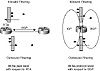
Figure 5-23 Inbound outbound filtering example.At the peer level, inbound filtering indicates that the BGP speaker is filtering routing updates coming from other peers, whereas outbound filtering limits the routing updates advertised from the BGP speaker to other peers. Filtering behavior is the same whether the BGP peers are external (EBGP) or internal (IBGP).
At the protocol level, inbound filtering limits the routing updates being injected into a protocol. Outbound filtering limits the routing updates being injected from this protocol. With respect to BGP, for example, inbound filtering limits the updates being redistributed from other protocols such as IGP and static into BGP. Outbound filtering limits the updates being redistributed from BGP into IGP.
Route Filtering and Manipulation Process
Filtering and manipulating a route or a set of routes involves three actions:
- 1. See Identifying Routes
- 2. See Permitting or Denying the Routes
- 3. See Manipulating Attributes
- 2. See Permitting or Denying the Routes
Notes:
Cisco uses the concept of route maps to achieve filtering and attribute manipulation. Route maps are discussed in Chapter 10, "Configuring Basic BGP Function and Attributes."
Identifying Routes
Identifying routes is the process of setting criteria to differentiate routes from each other. Such criteria could be based on the IP prefix of the route, the autonomous system from which a route was originated, a list of ASs a route has passed through, a specific attribute value inside the route, and so on. A list of criteria instances is contained in the filtering rules, and a route is compared to the first instance in the list. If the route does not match the first instance, it is checked against the next instance in the list. After a route matches an instance, it is considered identified and will not be compared to any further instances.
If the route proceeds to be compared against the entire list of instances and there is still no match, then the route is discarded.
Identifying routes based on the Network Layer Reachability Information (NLRI) or the AS_path list or both is the most common way of identifying routes. Each of these methods is discussed in more detail in the following sections, "See Identifying Routes Based on the NLRI" and "See Identifying Routes Based on the AS_Path."
Permitting or Denying the Routes
After the route has been identified, action can be taken upon it. The route is permitted or denied, depending on what filtering rules have been established for that juncture. The criteria for permitting or denying routes depends on the policies an AS is setting. If the route is permitted, then it is either accepted "as is," or submitted for modification of attributes, again, depending on what policies are to be set. If the route is denied, then that route is discarded.
Manipulating Attributes
If a route is permitted, its attributes can be changed to affect the decision process. In earlier sections, you saw how attributes such as local preference and MED can be added or made larger or smaller to prefer a route over another. As you will see later on, attribute manipulation is key to establishing route policies, load balancing, and route symmetry.
Figure 5-24 explains in detail how multiple instances can be applied on a set of routes to find a match. Note that each instance could have one or more criteria. A route could be checked based on its prefix and its AS_path information, for example.
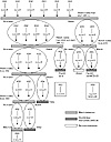
Figure 5-24 Summary example of route filtering and manipulation process.Also note that after a route matches, it is not compared to any more instances. Hence, the order in which the instances are checked is important. An instance that permits all routes for example, if put at the beginning of the list, will override all the other instances.
Identifying Routes Based on the NLRI
A BGP route could be identified by its Network Layer Reachability Information (NLRI), which is the prefix and the mask, as discussed in Chapter 4, "Interdomain Routing Basics." For filtering purposes, a prefix or a range of prefixes is defined. If the route falls within the range, it will be identified.
Troubleshooting:
Example: Ch. 10, pp. 308-310. Identifying and Filtering Routes Based on the NLRI
Figure 5-25 illustrates filtering criteria of 10.1.0.0 0.0.255.255, which represents a range of routes identified by a prefix 10.1.0.0 and an inverse mask 0.0.255.255. The 0s in the mask indicate a match, whereas the 1s indicate a do-not-care-bit. The 10.1.0.0 0.0.255.255 range will identify all routes of the form 10.1.X.X. Presented with the prefixes shown in figure 5-25, this filter will identify 10.1.1.0/24, 10.1.2.0/24, and 10.1.2.2/30, and will exclude 11.2.0.0/16 and 12.1.1.0/24.
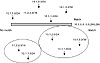
Figure 5-25 NLRI filtering criteria example.Identifying Routes Based on the AS_Path
Identifying routes based on the AS_path information is a bit more involved. As you know by now, the AS_path list is a list of ASs that a route has traversed before reaching a BGP peer. The list itself is a character string that contains characters from the following set: 0,1,2,3,4,5,6,7,8,9, "space," left brace "{", right brace "}", left parenthesis "(", right parenthesis ")", the beginning of the input string, the end of the input string, and a comma ",".
Troubleshooting:
Example: Ch. 10, pp. 310-312. Identifying and Filtering Routes Based on the AS_Path
The AS_path list 10 2, for example, is actually: a beginning of string character followed by character 1 followed by a 0 followed by a space followed by a 2 followed by an end of string character.
Trying to identify the AS_path list consists of comparing the list to what is called a regular expression. A regular expression is just a pattern of characters represented by a formula such as: ^200 100$, which is a regular expression representing a list that starts with 200, followed by a space, and then ends with 100. The "^" and the "$" are representations of the beginning and end of string characters, respectively.
A regular expression can be formed by using single-character patterns or multiple-character patterns.
Single-Character Patterns
A single-character pattern tries to match a single character. The single-character regular expression 3 tries to match the character 3 in an input string. You can specify a range of single characters to match against a string. Ranges are included within brackets ([]). The order in which the characters forming the range get listed is not important. The regular expression consisting of the range [efghEFGH], for example, is trying to match any of the above characters in an input string. Given the two input strings, "hello" and "there," the regular expression matches both of these lists because they both contain the character e.
Ranges can be listed by typing the end points of a range; for example, ranges [a-z] and [0-9] indicate any lowercase character between a and z and any numeric character between 0 and 9, respectively.
You can also reverse or negate the pattern matching by including a caret (^) at the beginning of the range. The range [^a-dA-D], for example, matches any character except a,b,c,d,A,B,C,D. Some characters have a special meaning, such as the dollar sign $ and the underscore _, as described in table 5-4.
Table 5-4 Regular expression special characters
Character Symbol Special Meaning
Period . Matches any single character, including white space. Asterisk * Matches 0 or more sequences of the pattern. Plus sign + Matches 1 or more sequences of the pattern. Question mark ? Matches 0 or 1 occurrences of the pattern. Caret ^ Matches the beginning of the input string. Dollar sign $ Matches the end of the input string. Underscore _ Matches a comma (,), left brace ({), right brace (}), left
parenthesis, right parenthesis, the
beginning of the input string, the end of the input string, or a space.Brackets [range] Designates a range of single-character patterns. Hyphen - Separates the end points of a range.
To list the special characters as part of an input list, they need to be preceded with a backslash (\). The range [abc\$], for example, will match an input string that contains the characters a,b,c, and $. Table 5-4 lists the special characters used in regular expressions.
Multiple-Character Patterns
Multiple-character regular expressions are just an ordered sequence of single-character patterns. The pattern is a combination of letters, numbers, any keyboard character, and special meaning characters. An example of a multiple-character regular expression follows: 100 1[0-9] . This regular expression matches any string that contains the exact sequence 100, followed by a space, followed by 1, followed by any number between 0 and 9. Any of the following input strings will match the regular expression: 123 100 10 11, or, 100 19, or 19 100 11 200, and so on.
Building Complex Regular Expressions
The special characters in table 5-4 can be used to build complex but very practical regular expressions. The caret (^) and ($) dollar sign are used to match the regular expression pattern against the beginning and the end of the input string. Other characters such as the asterisk (*), the plus sign (+), and the question mark (?) enable you to repeat the patterns inside the regular expression.
The following example matches any number of occurrences of the letter "a," including none:
- • a* is equivalent to any of the following: (nothing), a, aa, aaa, aaaa, and so on.
The following example requires that at least one letter "a" be present in the string to be matched:
- • a+ is equivalent to a, aa, aaa, aaaa, and so on.
The following is an example of a list that may or may not contain the letter "a:"
- • ba?b is equivalent to bb or bab.
To repeat instances of multiple-character patterns, the pattern is enclosed in parentheses; for example, the expression (ab)+ is equivalent to ab or abab.
The underscore character (_) matches the beginning of a string (^), the end of a string ($), parentheses (), space, braces, comma, or underscore. The dot character matches a single character, including a white space. Figure 5-26, table 5-5, and table 5-6 illustrate how characters can be strung together to create a useful regular expression.
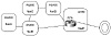
Figure 5-26 Network topology for complex regular expression example.Consider the network topology illustrated in figure 5-26. AS400, AS300, AS200, AS100, and AS50 are originating the routes NetA, NetB, NetC, NetD, and NetE, respectively. RTA in AS50 is receiving updates about all these networks from its neighbors AS100 and AS300. After running its BGP decision process, RTA has picked the best path to reach these networks according to table 5-5.
Table 5-5 Best BGP route selection for RTA.
Network AS_path
NetA 300 400 NetB 300 NetC 100 200 NetD 100 NetE empty
Table 5-6 reflects the regular expressions that would be used to create possible route filtering arrangements that RTA could apply when propagating routes to the NAP.
Table 5-6 Expressions and Resulting Outcomes for Regular Expressions Example. Routes to be Advertised from RTA to the NAP Expression Path Info Outcome Local routes only ^$ empty NetE All routes .* all paths NetA, NetB, NetC,
NetD, NetERoutes that originated from directly connected customers ^300$
^100$300
100NetB, NetD Connected customer routes and their customers' routes ^300_
^100_300 400
300
100 200
100NetA, NetB, NetC,
NetDRoutes that originated in AS200 _200$ 100 200 NetC Routes that passed via AS100 _100_ 100 200
100NetC, NetD
Notes:
The ^$ expression indicates an empty path list, which is actually the local routes. The ^ and $ define the border of the string, and the underscore, such as in _200$, limits the AS number to being exactly 200 and not 1200 or 2200.
Filtering based on AS_path information is quite effective because it filters all the routing updates that belong to the AS_path at the same time. Without this type of filtering, thousands of routes would have to be listed individually.
Peer Groups
A BGP peer group is a group of BGP neighbors that share the same update policies. Instead of defining the same policies for each individual neighbor, you define a peer group name and assign policies to the peer group itself. An administrator, for example, setting policies toward its BGP peers will most probably set the same policies toward the majority of its peers, and therefore will define them as a peer group.
Not only do peer groups save the operator from repetitive configuration of each BGP peer, they save the BGP router itself from the effort of parsing the policies sequentially for each neighbor. With peer groups, the router formulates the UPDATE once, based on the policies of the peer group, and then floods the same UPDATE to all the neighbors that fall within the group.
In figure 5-27, RTA has three internal peers with which it has the same internal policies. RTA also has three external peers with which it has the same policies. RTA's configuration includes two sets of peer groups, one for inside the AS and one for outside the AS. Each peer group contains the set of policies that RTA has toward its peers. These policies could be a set of IP prefix filters or AS_path filters and possible attribute manipulation. After the peer groups have been defined, these policies are applied to the neighbors that make up the peer group.
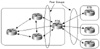
Figure 5-27 Peer group implementation.Due to the route update optimization that peer groups offer, some restrictions need to be followed for peer groups to work correctly with external BGP peers. If the following guidelines are not followed, loss of routing information could occur.
When the peer group consists of external neighbors (EBGP), the following restrictions must apply:
- • The hub router (such as RTA in figure
5-27) cannot be a transit router for the external ASs. In other
words, updates from one EBGP neighbor in the peer group should
not be passed to other EBGP neighbors in the same peer group.
- • All the EBGP peer group members should belong to the same IP subnet.
Peer Group Exceptions
Exceptions occur when some neighbors inside a peer group have slightly different policies from other neighbors. Additional policies can be added to the neighbor to complement the set of policies that fall within the peer group. Assume that RTA requires an additional set of filters to be set toward its peer RTB. RTA can apply the extra filters toward RTB while still keeping RTB within the external peer group.
Troubleshooting:
Example: Ch. 10, pp. 312-315. Peer Groups
BGP4 Aggregation
One of BGP4's main improvements over BGP3 and BGP2 is its capability to handle CIDR and supernetting. CIDR and supernetting were first discussed in Chapter 3, "Handling IP Address Depletion," with respect to controlling the growth of IP forwarding tables and the depletion of the IP address space.
Aggregation applies to routes that exist in the BGP routing table. This is in contrast to the network command, discussed earlier in this chapter, and which applies to routes that exist in the IP routing table. Aggregation can be performed if at least one more specific route of the aggregate exists in the BGP routing table.
Cisco Systems offers a variety of ways of manipulating aggregates to make sure that every need on the Internet is fulfilled. This section first examines simple aggregation techniques and then moves on to more complicated (but fun) scenarios.
Aggregate Only, Suppressing the More Specific
This scenario illustrates a case where an aggregate is advertised and all its specific routes are suppressed. This is usually done when the more specific routes do not offer any extra benefits, such as making better decisions in forwarding traffic. Figure 5-28 illustrates a situation in which all the routing updates are lumped into a single aggregate. Suppose that AS100 has the subnet ranges 172.16.0.0/24 to 172.16.15.0/24. This includes 172.16.0.X, 172.16.1.X, and so on. The list of specific attributes can be summarized into the range 172.16.0.0/20. The aggregate 172.16.0.0/20 is sent out, and all the more specific routes are suppressed.

Figure 5-28 BGP4 aggregation example suppression specific routes.
Troubleshooting:
Example: Ch. 10, pp. 343-346. Aggregate Only, Suppressing the More Specific
Aggregate Plus More Specific Routes
A number of situations exist in which an AS will send out an aggregate and its more specific routes. This usually occurs in situations where the customer is multihomed to a single provider. The provider would use the more specific routes to make better decisions when sending traffic toward the customer. At the same time, the provider can propagate the aggregate only toward the NAP to minimize the number of routes leaked to the Internet. This is illustrated in figure 5-29.
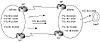
Figure 5-29 BGP4 aggregation including specific routes.
Troubleshooting:
Example: Ch. 10, pp. 346-352. Aggregate Plus More Specific Route
AS100 is multihomed with provider AS200 via the San Francisco and New York links. AS100 can send AS200 either the aggregate 172.16.0.0/20 only, or it can send the aggregate and all the more specific routes. If the aggregate only is sent over both the SF and NY links, then traffic from AS200 toward AS100 will always take one link or the other. This arrangement creates an unbalanced traffic load (balanced loading is discussed further in Chapter 6, "Redundancy, Symmetry, and Load Balancing"). To balance the load, AS100 sends the aggregate and all the more specific routes. Different metrics could be sent for different routes on each of the links. This way, based on the specific network number, AS200 can decide whether to use the SF or NY link when trying to reach AS100.
To avoid complicating routing tables beyond the provider level, more specific routes from customers are usually stopped at the provider level. AS200 would propagate only the aggregate 172.16.0.0/20 toward the NAP and suppress the more specific routes.
Usually providers like to minimize configuration and administration. In this situation, a dynamic approach can be used to stop all the more specific routes from being propagated to the NAP. This is done by having AS100 tag all the more specific updates with the community attribute NO-EXPORT while leaving the aggregate as is. This is illustrated in figure 5-30.
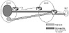
Figure 5-30 Community no-export route aggregation example.When AS200 gets the updates from AS100, it will recognize the community as a request not to forward the updates to its external peers. The aggregate will be propagated as usual to the NAP and other peers.
Aggregate with a Subset of the More Specific Routes
In some situations, a subset of the more specific routes needs to be advertised in addition to the aggregate. Figure 5-31 illustrates a situation in which this might be useful.
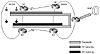
Figure 5-31 Aggregation example including subset of specific routes.In figure 5-31, AS100 is multihomed to AS200. AS100 would like the networks in the vicinity of SF to be accessed via the SF link and the networks in the vicinity of NY to be accessed via the NY link. This could be achieved in the following manner:
- • On the SF link, advertise the aggregate
and the SF networks only.
- • On the NY link, advertise the aggregate and the NY networks only.
Troubleshooting:
Example: Ch. 10, pp. 352-356. Aggregate with a Subset of the More Specific Routes
In this case, AS200 can only reach the SF networks via the SF link and the NY networks via the NY link. Networks in other locations could be sent on both links or either link. In case of a link failure, all networks can still be reached by following the aggregate route, which is advertised on both links. The no-export technique, discussed in the previous example, can be used to propagate only the aggregate to the NAP.
Loss of Information Inside Aggregates (AS-SET)
Aggregation causes loss of information due to the fact that the attributes of individual routes that form the aggregate will be lost. As already discussed in this chapter, BGP defines an AS-SET, which is a mathematical set consisting of all elements contained in all paths that are being summarized. An example of such elements are the AS_path and community attributes.
Troubleshooting:
Example: Ch. 10, pp. 356-359. Loss of Information Inside Aggregates (AS-SET)
Using AS-SET with the aggregate will cause additional route instabilities due to the fact that changes in the attributes of the individual routes being summarized will now translate into changes of the aggregate itself and will cause the aggregate to be constantly withdrawn and updated.
Changing the Attributes of the Aggregate
In some situations, it is required that the attributes of the aggregate be changed. One such situation is when the aggregate contains some unwanted attributes that it inherited from the routes it is summarizing (in case of AS-SET). An example could be a "NO-EXPORT" community attribute that the aggregate got from one of the more specific routes and that causes the aggregate not to be exported to other ASs. Another situation that calls for changing the attributes of the aggregate is to reflect a level of preference for a certain aggregate. An example would be of customer's advertising an aggregate via multiple links to a certain provider. The customer might like to have the aggregate go out with different MEDs on different links to influence the entrance point into the AS. Cisco has developed techniques to enable the user to modify the attributes of an aggregate accordingly.
Troubleshooting:
Example: Ch. 10, pp. 360-362. Changing the Attributes of the Aggregate
Forming the Aggregate Based on a Subset of More Specific Routes
You have seen that with AS-SET the aggregate will contain a set of all attributes (including AS numbers) that exist in the individual routes being summarized. If the aggregate is summarizing routes that come from different ASs, it becomes useful to specify which routes are being included in forming the aggregate. This would help in a hub and spoke situation where each of the leaf ASs contains a separate subset of the aggregate that is originated by the hub. When forming the aggregate, the hub AS would exclude the more specific routes that belong to the leaf AS that needs to receive the aggregate. The aggregate received by the leaf AS would not contain the AS number of the leaf AS, and hence it is not discarded. Figure 5-32 gives an example of where this could be used.
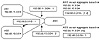
Figure 5-32 Forming aggregate based on a subset of more specifics.AS3 is a hub AS receiving routes 192.68.11.0/24 and 192.68.10.0/24 from the leaf ASs AS1 and AS2. Prefix 192.68.11.0/24 has an AS_path of 1, and 192.68.10.0/24 has an AS_path of 2. When the AS-SET aggregate is being formed by AS3 based on all the more specific routes, the AS_path information would be {1 2}. The aggregate itself, if sent back to either AS1 or AS2, would be discarded for loop prevention. AS1 will see its AS number in the AS_path information and would drop the update; the same is true for AS2. If you are able to specify which more specific routes can form the aggregate, then you could, for example, specify that the aggregate is to be formed based on 192.68.11.0/24 only. This way, the AS_path information would be 1 and would not contain AS2. The aggregate can now be sent back to AS2 with no problem. AS2 can use this aggregate to forward traffic to all destinations in AS1.
Troubleshooting:
Example: Ch. 10, pp. 363-365. Forming the Aggregate Based on a Subset of More Specific Routes
Looking Ahead
Having mastered the basics of routing protocols and examined the particular configuration tools of BGP, you are now in a position to begin applying these tools to specific internetworking topologies. In doing so, you will be juggling a number of overarching design goals—redundancy, symmetry, and load balancing—that are of varying importance depending on a particular network's needs and that sometimes conflict with one another. The meaning of these design goals is discussed in more detail in the next chapter. The attributes covered in this chapter are used in the following chapter to achieve the desired routing design goals.
Tuning BGP capabilities to satisfy a network's needs involves looking outside the AS as well as inside. That is, the policies set by the networks to which you are interconnected, although usually outside your direct control, have practical implications for how you configure BGP at your end. All this becomes clearer in the next chapter, which covers multiple redundancy, symmetry, and balancing scenarios by presenting architectures commonly used on the current Internet.
Frequently Asked Questions
Q—If my IBGP peers are not directly connected, do I have to use EBGP multihop?
A—No. There is no restriction on IBGP peers to be connected. EBGP multihop is for EBGP only.
Q—Should I inject my BGP routes into the IGP for synchronization to take effect?
A—No. Injecting the BGP into your IGP is not recommended. You should turn the synchronization off. Make sure that this will not result in reachability problems inside your AS.
Q—Does listing my IGP routes via the network command rather than redistributing the IGP into BGP give my BGP routes more stability?
A—No. In both methods, the fluctuation of your IGP routes will translate in fluctuation in your BGP routes. The network command only gives you better control and less worry about what your IGP might carry into BGP if you use redistribution.
Q—Do I have to list my connected interfaces by using the network command?
A—If you want the directly connected subnets to be reachable via BGP, then you can advertise them; if not, you don't have to.
Q—I have two border routers talking EBGP to my provider and IBGP internally. If I list my IGP routes via the network command on both routers, would that create a loop on the IBGP session?
A—No, you will not create a loop. Actually, doing so gives you more redundancy. If one of your border routers fails, the other border router will still announce the same networks.
Q—What happens if I use next-hop-self on my EBGP peers?
A—Next-hop-self is used between IBGP peers. Using it between EBGP peers is a not an option because the next hop is always the IP address of the EBGP neighbor.
Q—I need to receive only a few updates from my neighbor; can I filter on my side of the link?
A—Yes, you can. Ask your neighbor to send you only the routes you need to minimize unnecessary link bandwidth usage and unnecessary route fluctuations. At the same time, use filtering on your end to protect yourself from potential accidents where your neighbor sends you more routes than you are expecting.
Q—My provider needs me to send him different local preference on different links; is that possible?
A—No. Local preference is defined inside the AS and is not carried on EBGP sessions.
Q—I am receiving MED from my provider that is influencing my traffic in a way that conflicts with my IGP. What do I do?
A—If receiving MEDs is causing you problems, call your provider and ask him to stop sending MEDs. Or, you can set MED to 0 on your end of the session.
Q—I am connected to multiple providers. On some occasions, my AS gets hit with an enormous amount of traffic that does not belong to my AS. What could be wrong?
A—You might be advertising routes that you receive from one provider to other providers. Other ASs might be using your AS as transit for their traffic. Make sure that you advertise only your routes to your providers.
Q—I am multihomed to the same provider. Do I have to worry about advertising the routes I learn from one link back on the second link?
A—BGP on your provider's end will detect that the routes it is receiving from you have passed through its AS already and will ignore them. Nevertheless, this is bad practice. You should not overload the links and routers with useless information; make sure that you send your own routes only.
Q—I am a provider, and I have given one of my customers a private AS number. Now, the customer wants to have a different connection with another provider. What would happen if he keeps using a private AS number?
A—This would be an illegal configuration. After you advertise this customer's network to the Internet, you are stripping the private AS number and announcing the routes as if they originated from your own AS. If the second provider does the same thing, then the customer's networks will have two origins—your AS and the AS of the other provider—and that is illegal.
Q—I am connected to one provider in San Francisco, and I am advertising my routes via BGP. I am connecting to another provider in LA. Should I get a different AS number?
A—If both the SF and LA networks fall under the same administration and have the same policies with other ASs, then they belong in the same AS. Remember that dividing networks via BGP is to define the boundaries of administration and policy. Geographical location is not the deciding factor.
- 2. Prefer the path with the largest weight (weight is a Cisco proprietary parameter).


