Chapter 4. Routing Protocol Basics
A brief consideration of interior gateway protocols as a point of contrast for this chapter's more in-depth consideration of exterior gateway protocols.
An autonomous system is a set of routers sharing the same routing policies. Various configurations for autonomous systems are possible, depending on how many exit points to outside networks are desired and whether the system should permit through traffic.
An overview of how the Border Gateway Protocol (version 4) operates, including its message header format, and how and what it negotiates with neighboring routers. The formats and purposes of BGP's four main message types—OPEN, NOTIFICATION, KEEPALIVE, and UPDATE—are covered.
Interdomain Routing Basics
The Internet is a collection of autonomous systems that define the administrative authority and the routing policies of different organizations. Autonomous systems run Interior Gateway Protocols (IGPs), such as RIP, IGRP, EIGRP, OSPF, and ISIS, within their boundaries and interconnect via an Exterior Gateway Protocol (EGP) called the Border Gateway Protocol (BGP).
Routers are devices that direct traffic between hosts. Routers build routing tables that contain their collected information on all the best paths to all the destinations they know how to reach. They both announce and receive route information to and from other routers. This information goes into the routing tables.
Overview of Routers and Routing
Routers develop a hop-by-hop mechanism by keeping track of "next hop" information that enables a data packet to find its destination through the network. A router that does not have a direct physical connection to the destination checks its routing table and forwards the packet to another next hop router that is closer to that destination. The process repeats until the traffic finds its way through the network to its final destination.
EGPs, such as BGP, were introduced because IGPs do not scale in networks that go beyond the enterprise level. IGPs were never designed for the purpose of global internetworking because they do not have the necessary hooks to segregate enterprises into different administrations that are technically and politically independent from one another. This chapter touches upon basic IGP functionality and then explains the specifics of BGP.
Figure 4-1 describes three routers, RTA, RTB, and RTC, connecting three local area networks, 192.10.1.0, 192.10.5.0, and 192.10.6.0, via serial links. Each serial link is repesented by its own network number, which results in three additional networks, 192.10.2.0, 192.10.3.0, and 192.10.4.0. Each network has a metric associated with it indicating the level of overhead (cost) of transmitting traffic on that particular link. The link between RTA and RTB, for example, has a cost of 2,000, much higher than the cost of 60 of the link between RTA and RTC. In practice, the link between RTA and RTB is a 56 Kbps link with much bigger delays than the T1 link between RTA and RTC and the T1 link between RTC and RTB combined.
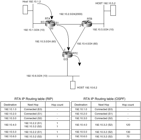)
Figure 4-1 Basic routing
behavior.
Routers RTA, RTB, and RTC would exchange network information via some interior gateway protocol and build their respective IP routing tables. Figure 4-1 shows examples of RTA's IP routing table for two different scenarios; the routers are exchanging routing information via RIP in one scenario and OSPF in another.
As an example of how traffic is passed between end stations, if host 192.10.1.2 is trying to reach host 192.10.6.2, it will first send the traffic to RTA. RTA will look in its IP routing table for any network that matches this destination and would find that network 192.10.6.0 is reachable via next hop 192.10.3.2 (RTC) out on Serial line 2 (S2). RTC would receive the traffic and would try to look for the destination in its IP routing table (not shown). RTC would discover that the host is directly connected to its Ethernet 0 interface (E0) and would send the traffic to 192.10.6.2.
In the preceding example, the routing is the same whether RTA is using the RIP or OSPF scenario. RIP and OSPF, however, fall into different categories of IGP protocols, namely distance vector protocols and link state protocols, respectively. For a different routing example in figure 4-1, the results might be different depending on whether you are looking at the RIP or OSPF scenario. It is useful at this point to consider characteristics of both IGP protocol categories, to see how protocols generally have evolved to meet increasingly sophisticated routing demands.
Distance Vector Protocols
Distance vector protocols such as RIP version 1 were mainly designed for small network topologies. The term distance vector derives from the fact that the protocol includes in its routing updates a vector of distances (hop counts). By using hop counts, distance vector protocols do not factor into the routing equation the overhead of sending information over a particular link. Low-speed links are treated equally or sometimes preferred over a high-speed link, depending on the calculated hop count in reaching a destination. This would lead to suboptimal and inefficient routing behaviors.
Consider, for example, the RTA routing tables shown in figure 4-1. In the RIP case, RTA has listed the direct link between RTA and RTB to reach network 192.10.5.0. RTA prefers this link because it requires just one hop via RTB versus two hops via RTC and then RTB. But the preferred route is inefficient because the total cost of the routing path via RTC and then RTB (60 + 60 = 120) is much less than the cost of crossing the RTA-RTB link (2,000).
Another issue with hop counts is the count to infinity restriction: distance vector protocols have a finite limit of hops (15) after which a route is considered unreachable. This would restrict the propagation of routing updates and would cause problems for large networks.
The reliance on hop counts is one deficiency of distance vector protocols; another deficiency is the way that the routing information gets exchanged. Distance vector algorithms work on the concept that routers exchange all the network numbers they can reach via periodic broadcasts of the entire routing table. In large networks, the routing table exchanged between routers becomes very large and very hard to maintain, leading to slower convergence.
Convergence refers to the point in time at which the entire network becomes updated to the fact that a particular route has appeared or disappeared. Distance vector protocols work on the basis of periodic updates and hold-down timers: If a route is not received in a certain amount of time, the route goes into a hold-down state and gets aged out of the routing table. The hold-down and aging process translates into minutes in convergence time before the whole network detects that a route has disappeared. The delay between a route's becoming unavailable and its aging out of the routing tables can result in routing loops and black holes.
Another major drawback of distance vector protocols is their classfull nature and their lack of support of Variable Length Subnet Masks or CIDR. Distance vector protocols do not exchange mask information in their routing updates. A router that receives a routing update on a certain interface will apply to this update its locally defined subnet mask. This would lead to confusion, in case the interface belongs to a network that is variably subnetted, and a misinterpretation of the received routing update.
Finally, distance vector networks are considered to be flat. They present a lack of hierarchy, which translates into a lack of aggregation. This flat nature has made distance vector protocols incapable of scaling to larger and more efficient enterprise networks.
RIP version 2 has added support for VLSM and CIDR, but it still carries most of the other deficiencies that its predecessor, RIP version 1, has.
Link State Protocols
Link state protocols, such as the Open Shortest Path First (OSPF) [1] and Intermediate System-to-Intermediate System (ISIS) [2], are more advanced routing protocols that have addressed the deficiencies of distance vector protocols. Link state protocols work on the basis that routers exchange information elements, called link states, which carry information about links and nodes. This means that routers running link state protocols do not exchange routing tables. Each router inside a domain will have enough bits and pieces of the big puzzle that it can run a shortest path algorithm and build its own routing table.
Following are some of the benefits that link state protocols provide over distance vector protocols:
- • No hop count—No limits on the number of
hops a route can take. Link state protocols work on the basis of
metrics rather than hop counts.
As an example of a link state protocol's reliance on metrics rather than hop count, turn again to the RTA routing tables shown in figure 4-1. In the OSPF case, RTA has picked the optimal path to reach RTB by factoring in the cost of the links. Its routing table lists the next hop of 192.10.3.2 (RTC) to reach 192.10.5.0 (RTB). This is in contrast to the RIP scenario, which resulted in a suboptimal path.- • Bandwidth representation—Link bandwidth and delays are factored in when calculating the shortest path to a certain destination. This leads to better load-balancing based on actual link cost rather than hop count.
- • Better convergence—Link and node changes are flooded into the domain via link state updates. All routers in the domain will immediately update their routing tables.
- • Support for VLSM and CIDR— Link state protocols exchange mask information as part of the information elements that are flooded in the domain. As a result, networks with variable length masks can be easily identified.
- • Better hierarchy—Whereas distance vector networks are flat networks, link state protocols divide the domain into different levels and areas. This hierarchical approach provides better control over network instabilities and a better mechanism to summarize routing updates across areas, specifically, by lumping multiple contiguous routing updates into supersets of routing updates called aggregates.
- • Bandwidth representation—Link bandwidth and delays are factored in when calculating the shortest path to a certain destination. This leads to better load-balancing based on actual link cost rather than hop count.
Even though link state algorithms have provided better routing scalability, which enables them to be used in bigger and more complex topologies, they still should be restricted to interior routing. Link state protocols, by themselves, cannot provide a global connectivity solution required for Internet interdomain routing. In very large networks and in case of route fluctuation caused by link instabilities, link state retransmission and recomputation will become too large for any router to handle.
Multihomed Nontransit AS
An AS is multihomed if it has more than one exit point to the outside world. An AS can be multihomed to a single provider or multiple providers. A nontransit AS does not allow transit traffic to go through it. Transit traffic is any traffic that has a source and destination outside the AS. Figure 4-5 illustrates an AS (AS1) that is nontransit and multihomed to two providers, ISP1 and ISP2.
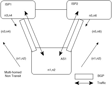
Figure 4-5 Multihomed
nontransit AS example.
A nontransit AS would only advertise its own routes and would not advertise routes that it learned from other ASs. This ensures that traffic for any destination that does not belong to the AS would not be directed to the AS. In figure 4-5, AS1 is learning about routes n3 and n4 via ISP1 and routes n5 and n6 via ISP2. AS1 is only advertising its local routes (n1,n2) and is not passing to ISP2 routes it learned from ISP1 or to IPS1 routes it learned from ISP2. This way, AS1 will not open itself to outside traffic, such as ISP1 trying to reach n5 or n6 and ISP2 trying to reach n3 and n4 via AS1. Of course, ISP1 or ISP2 can force their traffic to be directed to AS1 via default or static routing. As a precaution against this, AS1 could filter any traffic coming toward it with a destination not belonging to AS1.
Multihomed nontransit ASs do not really need to run BGP4 with their providers, although it is recommended and most of the time required by the provider. As you will see later on in this book, running BGP4 with the providers has many advantages in controlling route propagation and filtering.
Multihomed Transit AS
A multihomed transit AS has more than one connection to the outside world and can still be used for transit traffic by other ASs (see figure 4-6). Transit traffic (relative to the multihomed AS) is any traffic with an origin and destination that does not belong to the AS.

Figure 4-6 Multihomed
transit AS using BGP internally and externally.
Even though BGP4 is an exterior gateway protocol, it can still be used inside an AS as a pipe to exchange BGP updates. BGP connections inside an autonomous system are called Internal BGP (IBGP), whereas BGP connections between autonomous systems are called External BGP (EBGP). Routers that are running IBGP are called transit routers when they carry the transit traffic going through the AS. Routers that run EBGP with other ASs are usually called border routers.
A transit AS would advertise to one AS routes that it learned from another AS. This way, the transit AS would open itself to traffic that does not belong to it. Multihomed transit ASs are advised to use BGP4 for their connections to other ASs and also internally to shield their internal nontransit routers from Internet routes. Not all routers inside a domain need to run BGP; internal nontransit routers could run default routing to the BGP routers, which alleviates the number of routes the internal nontransit routers must carry.
Figure 4-6 illustrates a multihomed transit autonomous system, AS1, connected to two different providers, ISP1 and ISP2. AS1 is learning routes n3, n4, n5, and n6 from both ISP1 and ISP2 and in turn advertising all that it learned, including its local routes, to ISP1 and ISP2. In this case, ISP1 could use AS1 as a transit AS to reach networks n5 and n6, and ISP2 could use AS1 to reach networks n3 and n4.
Border Gateway Protocol Version 4
BGP went through different phases and improvements from its earlier version, BGP1, in 1989 to today's version, BGP4, deployment of which started in 1993. BGP4 is the first version that handles aggregation (CIDR) and supernetting, as discussed earlier in this book.
BGP imposes no restrictions on the underlying Internet topology. It assumes that routing within an autonomous system is done via an intra-autonomous system routing protocol. (For the purposes of this book, intra means routing within an entity, and inter means between entities.) BGP constructs a graph of autonomous systems based on the information exchanged between BGP neighbors. This directed graph environment is sometimes referred to as a tree. As far as BGP is concerned, the whole Internet is a graph of ASs, with each AS identified by an AS number. Connections between two ASs together form a path, and the collection of path information forms a route to reach a specific destination. BGP ensures that loop-free interdomain routing is maintained. Figure 4-7 illustrates this general path tree concept.
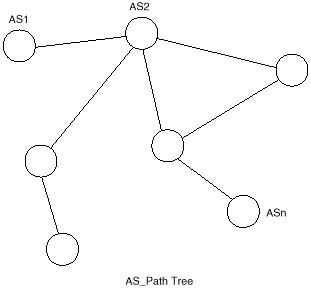
Figure 4-7 Example
AS_Path tree.
How BGP Works
BGP is a path vector protocol used to carry routing information between autonomous systems. The term path vector comes from the fact that BGP routing information carries a sequence of AS numbers, which indicates the path a route has traversed. BGP uses TCP as its transport protocol (port 179). This ensures that all the transport reliability such as retransmission is taken care of by TCP and does not need to be implemented in BGP itself.
Two BGP routers form a transport protocol connection between each other. These routers are called neighbors or peers. Figure 4-8 illustrates this relationship. Peer routers exchange multiple messages to open and confirm the connection parameters, such as the BGP version running between the two peers (for example, version 3 for BGP3 and version 4 for BGP4). In case of any disagreement between the peers, notification errors are sent, and the peer connection does not get established.
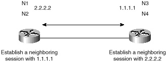
Figure 4-8 BGP routers
become neighbors.
Initially, all candidate BGP routes are exchanged, as illustrated in figure 4-9. Incremental updates are sent as network information changes. The incremental update approach has shown an enormous improvement as far as CPU overhead and bandwidth allocation compared with complete periodic updates used by previous protocols, such as EGP.
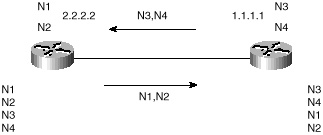
Figure 4-9 Exchanging all
routing updates.
Routes are advertised between a pair of BGP routers in UPDATE messages. The UPDATE message contains, among other things, a list of <length, prefix> tuples that indicate the list of destinations reachable via each system. The UPDATE message also contains the path attributes, which include such information as the degree of preference for a particular route.
In case of information changes, such as a route being unreachable or having a better path, BGP informs its neighbors by withdrawing the invalid routes and injecting new routing information. As illustrated in figure 4-10, withdrawn routes are part of the UPDATE message. These are the routes no longer available for use. Figure 4-11 illustrates a steady state situation: if no routing changes occur, the routers exchange only KEEPALIVE packets.
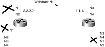
Figure 4-10 N1 goes down;
partial update sent.

Figure 4-11 Steady state;
N1 is still down.
Troubleshooting:
The meaning of rapidly incrementing table versions.
KEEPALIVE messages are sent periodically between BGP neighbors to ensure that the connection is kept alive. KEEPALIVE packets (19 bytes each) should not cause any strain on the router CPU or link bandwidth as they consume a minimal bandwidth (about 2.5 bits/sec for a periodic rate of 60 sec).
BGP keeps a table version number to keep track of the instance of the BGP routing table. If the table changes, BGP will increment the table version. A table version that is incrementing rapidly is usually an indication of instabilities in the network.
BGP Message Header Format
The BGP message header format is a 16-byte marker field, followed by a 2-byte length field and a 1-byte type field. Figure 4-12 illustrates the basic format of the BGP message header.
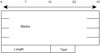
Figure 4-12 BGP message
header format.
There may or may not be a data portion following the header, depending on the message type. KEEPALIVE messages, for example, consist of the message header only, with no following data.
The marker field is used to either authenticate incoming BGP messages or to detect loss of synchronization between two BGP peers. The marker field can have two formats:
- • If the type of the message is OPEN or if
the OPEN message has no authentication information, the marker
field must be all ones.
- • Otherwise, the marker field will be computed based on part of the authentication mechanism used.
The length indicates the total BGP message length including the header. The smallest BGP message is no less than 19 bytes (16+2+1) and no greater than 4,096.
The type indicates the message type, from the following possibilities:
- • OPEN
- • UPDATE
- • NOTIFICATION
- • KEEPALIVE
- • UPDATE
The following sections examine the purpose and format of each of the four message types in more detail.
BGP Neighbor Negotiation
One of the basic steps of the BGP protocol is establishing neighbors between BGP peers. Without successful completion of this step, no exchange of updates will ever take effect. Neighbor negotiation is based on the successful completion of a TCP transport connection, the successful processing of the OPEN message, and periodic detection of the KEEPALIVE messages.
OPEN Message Format
Figure 4-13 illustrates the format of the OPEN message. The descriptions that follow summarize each of its fields:
- • Version—A 1-byte unsigned integer that
indicates the version of the BGP protocol, such as BGP3 or BGP4.
During the neighbor negotiation, BGP peers agree on a BGP version
number. BGP peers will try to negotiate the highest common version
that they both support. Cisco Systems provides the option of
predefining the version negotiated to cut down on the negotiation
process. Setting the version statically is usually used when the
versions of the BGP peers are already known.
- • My Autonomous System—A 2-byte field that indicates the AS number of the BGP router.
- • Hold Time—The maximum amount of time in seconds that may elapse between the receipt of successive KEEPALIVE or UPDATE messages. The hold timer is a counter that increments from zero to the hold time value. Receipt of a KEEPALIVE or UPDATE message causes the hold timer to reset to zero. If the hold time for a particular neighbor is exceeded, the neighbor would be considered dead. The hold time is a 2-byte unsigned integer.
The BGP router negotiates with its neighbor to set the hold time at whichever value is lower—its own hold time or its neighbor's. The hold time could be 0, in which case the hold timer and the KEEPALIVE timers are never reset—that is, these timers never expire, and the connection is considered to be always up. If not set to zero, the minimum recommended hold time is three seconds.- • BGP Identifier—A 4-byte unsigned integer that indicates the sender's ID. In Cisco's implementation, this is usually the router ID (RID), which is calculated as the highest IP address on the router or the highest loopback address at BGP session startup. (Loopback address is Cisco's representation of the IP address of a virtual software interface that is considered to be up at all times, irrespective of the state of any physical interface.)
- • Optional Parameters—This is a variable length field that indicates a list of optional parameters used in BGP neighbor session negotiation. This field is represented by the triplet <Parameter Type, Parameter Length, Parameter Value> with lengths of 1-byte, 1-byte, and variable length, respectively. An example of optional parameters is the authentication information parameter (type1), which is used to authenticate the session with a BGP peer.
- • Optional Parameter Length—This is a 1-byte unsigned integer that indicates the total length in bytes of the Optional Parameters field. A length value of 0 indicates that no Optional Parameters are present.
- • My Autonomous System—A 2-byte field that indicates the AS number of the BGP router.
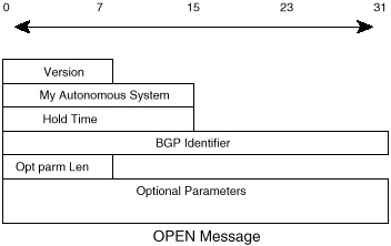
Figure 4-13 OPEN message
format.
Finite State Machine Perspective
BGP neighbor negotiation proceeds through different stages before the connection is fully established. Figure 4-14 illustrates a simplified finite state machine (FSM) that highlights the major events in the process with an indication of messages (OPEN, KEEPALIVE, NOTIFICATION) sent to the peer in the transition from one state to the other.

Figure 4-14 BGP neighbor
negotiation finite state machine.
The following discussions summarize the key states in the FSM example illustrated in Figure 4-14:
- 1. Idle—This is the first stage of the
connection. BGP is waiting for a Start event, which is normally
initiated by an operator. A Start event is usually caused by an
administrator establishing a BGP session through router
configuration or resetting an already existing session. After the
Start event, BGP initializes its resources, resets a connect retry
timer, initiates a TCP transport connection, and starts listening
for a connection that may be initiated by a remote peer. BGP then
transitions to a Connect state. In case of errors, BGP falls back
to the Idle state.
- 2. Connect—BGP is waiting for the transport protocol connection to be completed. If the TCP transport connection is successful, the state transitions to OpenSent (this is where the OPEN message is sent). If the transport connection is not successful, the state transitions to Active. If the connect retry timer expires, the state will remain in the connect stage, the timer will be reset, and a transport connection will be initiated. In case of any other event (initiated by system or operator), the state will go back to Idle.
- 3. Active—BGP is trying to acquire a peer by initiating a transport protocol connection. If it is successful, it will transition to OpenSent (an OPEN message is sent). If the connect retry timer expires, BGP will restart the connect timer and fall back to the connect state. Also, BGP is still listening for a connection that may be initiated from another peer. The state may go back to Idle in case of other events, such as a stop event initiated by the system or the operator.
In general, a neighbor state that is flip-flopping between Connect and Active is an indication that something is wrong with the TCP transport connection not taking effect. It could be because of many TCP retransmissions or the inability of a neighbor to reach the IP address of its peer.
Troubleshooting:
The meaning of flip-flopping between Conne and Active state
- 4. OpenSent—BGP is waiting for an OPEN message from its peer. The OPEN message is checked for correctness. In case of errors, such as a bad version number or an unacceptable AS, the system sends an error NOTIFICATION message and goes back to Idle. If there are no errors, BGP starts sending KEEPALIVE messages and resets the KEEPALIVE timer. At this stage, the hold time is negotiated, and the smaller value is taken. In case the negotiated hold time is 0, the hold timer and the KEEPALIVE timer are not restarted.
At the OpenSent state, the BGP will recognize, by comparing its AS number to the AS number of its peer, whether the peer belongs to the same AS (Internal BGP) or to a different AS (External BGP).
When a TCP transport disconnect is detected, the state will fall back to Active. For any other errors, such as an expiration of the hold timer, the BGP will send a NOTIFICATION message with the corresponding error code and will fall back to the Idle state. Also, in response to a stop event initiated by system or operator, the state will fall back to Idle.- 5. OpenConfirm—BGP waits for a KEEPALIVE or NOTIFICATION message. If a KEEPALIVE is received, the state will go to established, and the neighbor negotiation is complete. If the system receives an UPDATE or KEEPALIVE message, it restarts the hold timer (assuming that the negotiated hold time is not 0). If a NOTIFICATION message is received, the state falls back to Idle. The system will send periodic KEEPALIVE messages at the rate set by the KEEPALIVE timer. In case of any transport disconnect notification or in response to any stop event (initiated by the system or the operator), the state will fall back to Idle. In response to any other event, the system will send a NOTIFICATION message with an FSM (Finite State Machine) error code and will go back to Idle.
- 6. Established—This is the final stage in the neighbor negotiation. At this stage, BGP starts exchanging UPDATE packets with its peers. Assuming that it is non-zero, the Hold timer is restarted at the receipt of an UPDATE or KEEPALIVE message. If the system receives any NOTIFICATION message—that is, some error has occurred—the state will fall back to Idle.
The UPDATE messages are checked for errors, such as missing attributes, duplicate attributes, and so on. If errors are found, a NOTIFICATION is sent to the peer, and the state will fall back to Idle. In case the Hold timer expires, or a disconnect notification is received from the transport protocol, or a Stop event is received, or in response to any other event, the system will fall back to Idle. - 2. Connect—BGP is waiting for the transport protocol connection to be completed. If the TCP transport connection is successful, the state transitions to OpenSent (this is where the OPEN message is sent). If the transport connection is not successful, the state transitions to Active. If the connect retry timer expires, the state will remain in the connect stage, the timer will be reset, and a transport connection will be initiated. In case of any other event (initiated by system or operator), the state will go back to Idle.
NOTIFICATION Message
From the preceding examination of the finite state machine, it should be apparent that many opportunities exist among the various states, for errors to be detected. A NOTIFICATION message is always sent whenever an error is detected, after which the peer connection is closed. Network administrators will need to evaluate these NOTIFICATION messages to determine the specific nature of errors that emerge in the routing protocol. Figure 4-15 illustrates the general message format.

Figure 4-15 NOTIFICATION
message format.
The NOTIFICATION message is composed of the Error code (1-byte), Error subcode (1-byte), and a Data field (variable).
The Error code indicates the type of the notification, the Error subcode provides more specific information about the nature of the error, and the Data field contains data relevant to the error such as a bad header, an illegal AS number, and so on. Table 4-1 lists possible errors and their subcodes.
Troubleshooting:
Form and meaning of NOTIFICATION error messages
|
| |
|---|---|
| Error Code | Error Subcode |
|
| |
| 1—Message Header Error | 1—Connection Not Synchronized |
| 2—Bad Message Length | |
| 3—Bad Message Type | |
| 2—OPEN Message Error | 1—Unsupported Version Number |
| 2—Bad Peer AS | |
| 3—Bad BGP Identifier | |
| 4—Unsupported Optional Parameter | |
| 5—Authentication Failure | |
| 6—Unacceptable Hold Time | |
| 3—UPDATE Message Error | 1—Malformed Attribute List |
| 2—Unrecognized Well-Known Attribute | |
| 3—Missing Well-Known Attribute | |
| 4—Attribute Flags Error | |
| 5—Attribute Length Error | |
| 6—Invalid Origin Attribute | |
| 7—AS Routing Loop | |
| 8—Invalid NEXT_HOP Attribute | |
| 9—Optional Attribute Error | |
| 10—Invalid Network Field | |
| 11—Malformed AS_path | |
| 4—Hold Timer Expired | NOT applicable |
| 5—Finite State Machine Error (for errors detected by the FSM) | NOT applicable |
| 6—Cease (for fatal errors besides the ones already listed) | NOT applicable |
|
| |
KEEPALIVE Message
KEEPALIVE messages are periodic messages exchanged between peers to determine whether peers are reachable. As discussed previously, the hold time is the maximum amount of time that may elapse between the receipt of successive KEEPALIVE or UPDATE messages. The KEEPALIVE messages are sent at a rate that ensures that the hold time will not expire (the session is considered alive). A recommended rate is one-third of the hold time interval. If the hold time interval is zero, periodic KEEPALIVE messages will not be sent. The KEEPALIVE message is a 19-byte BGP message header with no data following it.
UPDATE Message and Routing Information
Central to the BGP protocol is the concept of routing updates. Routing updates contain all the necessary information that BGP uses to construct a loop-free picture of the Internet. The following are the basic blocks of an UPDATE message:
- • Network Layer Reachability Information
(NLRI)
- • Path attributes
- • Unreachable routes
- • Path attributes
Figure 4-16 illustrates these components in the context of an UPDATE message format.

Figure 4-16 BGP routing
update.
The NLRI is an indication, in the form of an IP prefix route, of the networks being advertised. The path attribute list provides BGP with the capabilities of detecting routing loops and the flexibility to enforce local and global routing policies. An example of the BGP path attributes is the AS_path attribute, which is a sequence of AS numbers a route has traversed before reaching the BGP router.
AS3 in figure 4-17, for example, is receiving BGP updates from AS2 indicating that network 10.10.1.0/24 (NLRI) is reachable via two hops, first AS2 and then AS1. Based on this information, AS3 will be able to direct its traffic to 10.10.1.0/24.

Figure 4-17 BGP routing
update example.
The third part of the UPDATE message, is a list of routes that have become unreachable—or in BGP terminology, WITHDRAWN. With the example illustrated in figure 4-17, if 10.10.1.0/24 is no longer reachable or experiences a change in its attribute information, BGP can withdraw the route that it advertised by sending an UPDATE message that lists the new network information or the network being unreachable.
Network Layer Reachability Information
BGP4 provides a new set of mechanisms for supporting classless interdomain routing (CIDR). As discussed in Chapter 3, "Handling IP Address Depletion," the concept of CIDR is a move from the traditional IP classes (A, B, C) toward a concept of IP prefixes. The IP prefix is an IP network address with an indication of the number of bits (left to right) that constitute the network number. The Network Layer Reachability Information (NLRI) is the mechanism by which BGP supports classless routing. The NLRI is the part of the BGP routing update that lists the set of destinations about which BGP is trying to inform its other BGP neighbors. The NLRI consists of multiple instances of the 2-tuples <length, prefix>, where length is the number of masking bits that a particular prefix has.
Figure 4-18 illustrates the NLRI <19, 198.24.160.0>. The prefix is 198.24.160.0, and the length is a 19-bit mask (counting from the far left of the prefix).

Figure 4-18 NLRI example.
Looking Ahead
The Border Gateway Protocol has defined the basis of routing architectures in the Internet. The segregation of networks into autonomous systems has logically defined the administrative and political borders between organizations. Interior Gateway Protocols can now run independently of each other, but still interconnect via BGP to provide global routing.
BGP as a protocol presents some basic elements of routing that are flexible enough to allow total control from the administrator's perspective. The power of BGP lies in its attributes and its route filtering techniques. Attributes are simply parameters that can be modified to affect the BGP decision process. Route filtering can be done on a prefix level or a path level. A combination of filtering and attribute manipulation can acheive the optimal routing behavior. Because traffic follows a road map laid out by routing updates, modifying the routing behavior would eventually modify the traffic trajectories. The next chapter, "Tuning BGP Capabilities," gives you a hands-on approach to understanding the basics of setting routing policies with BGP.
References
[1] RFC 1583 OSPF Version 2
[2] ISO 10589 Intermediate System-to-Intermediate System
[3] RFC 904 Exterior Gateway Protocol formal specification
[4] RFC 1771 A Border Gateway Protocol 4 (BGP-4)